

I. Introduction
Class IV flextensional transducers have been widely used as sound sources in underwater acoustics due to their excellent low frequency characteristics, high electro- acoustic conversion efficiency, and durability.[1,2,3] Recently, they have also gained attention as broadband receivers for underwater applications.[4] The structure of this transducer transmits the longitudinal vibration mode generated by a piezoelectric stack to an elliptical cylindrical shell, utilizing the amplification effect of flexural vibrations in the shell. As a result, conventional one dimensional analysis methods, such as equivalent circuit models, are inapplicable, rendering the mathematical analysis of characteristics considerably complex. While many studies have reported characteristic analyses using numerical methods, such as finite element analysis, to address this complexity, these approaches often require significant computational resources and time, making it challenging to optimize models or evaluate new designs efficiently.[5,6,7] A mathematical model for analyzing the characteristics of class IV flextensional transducers was proposed by Brigham;[8] however, its mathematical complexity has limited its practical applicability. Building upon this theory, Lam[9] proposed a relatively simpler analytical model. A theoretical formula for predicting the transducer’s resonant frequency was derived through numerical analysis, and corresponding prediction results were reported. However, this analytical expression was not experimentally validated. Moreover, several errors were identified in its theoretical formulation, and the analysis lacks sufficient consideration of the effects of structure variations in class IV flextensional transducers. Although several studies have investigated how changes in shell thickness influence the resonant frequency of such transducers, as mentioned earlier, there is a scarcity of research deriving the full frequency spectrum of input admittance.[8,10]
In the present study, we derive a corrected analytical expression for the mechanical impedance of an elliptical shell by conducting a mathematical analysis based on elliptical shell vibration theory.[9] Furthermore, we focus on a simplified class IV flextensional transducer to examine how variations in the thickness of its elliptical cylindrical shell affect its resonance characteristics, and we present experimental validation of the results.
II. Theoretical analysis
The structure of the class IV flextensional transducer used for theoretical analysis is shown in Fig. 1.[9]
The piezoelectric stack is modeled using a T-type equivalent circuit as illustrated in Fig. 2.[11] The mechanical impedance of the elliptical shell, /2, is represented by connecting it to both acoustic terminals of the equivalent circuit.
The impedance elements of the piezoelectric stack in the equivalent circuit are as follows.[11]
Here, the cross-sectional area of the piezoelectric stack is . When the sound velocity and density of the piezoelectric material are and respectively, the characteristic mechanical impedance of the piezoelectric material is , and the effective characteristic impedance for longitudinal effects is . The parameter represents the electromechanical coupling coefficient for longitudinal effects, and denotes the number of piezoelectric elements in the stack.
The effective wavenumber and sound velocity of the piezoelectric elements are given as follows.
Additionally, the electrical capacitance and the turns ratio of the transformer 𝜙, as shown in the equivalent circuit, are calculated as follows:
Meanwhile, for the insert with a length shown in Fig. 1, the quantities are represented in the equivalent circuit with the subscript . The impedance elements, characteristic mechanical impedance, wavenumber, and sound velocity are as follows.
Here, and represent the density and Young’s modulus, respectively. The mechanical impedance, , connected to both mechanical terminals of the equivalent circuit arises from the metal elliptical shell containing the piezoelectric stack, as shown in Fig. 1. Based on the previously reported findings, it can be derived as follows.
Here .
The in Eq. (5) is determined by the following matrix.
The elements of the matrix are given as follows.
Here , , , and are matrices that arise during the derivation of the determinant of the equation of motion. Although they do not have exact physical interpretations, their roles can be inferred from the governing equations. Specifically, is associated with the out-of-plane shear force coefficients, corresponds to in-plane force coefficients, relates to rotational moments, and represents external force coefficients. Superscript ‘N’ and ‘T’ denote components normal and tangential to the shell surface, respectively. Here, : Force applied to the cross-section of the piezoelectric stack, : Local radius of curvature, : Number of piezoelectric element.
III. Experiment and results
To validate the theoretical calculation model, an aluminum elliptical cylindrical shell resembling the structure in Fig. 1 was fabricated. As shown in Fig. 3(a), a semicircular groove was created to secure the piezoelectric stack. The elliptical cylindrical shell was manufactured using Computer Numerical Control (CNC) milling, and 4 types with thicknesses of 4 mm, 5 mm, 6 mm, and 8 mm were produced. Photo of one of these shells is shown in Fig. 3(b). A single piezoelectric stack was inserted into each shell, and the electrical input admittance was measured for each case. The length of the piezoelectric stack was measured to be 72.18 mm, but the distance between the semicircular grooves designed for securing the stack was 71 mm, as shown in Fig. 3(a). This was done to ensure good contact with the aluminum shell by applying prestress. However, the effect of this prestress was not considered in the theoretical calculations. During the insertion process, the aluminum shell was clamped and deformed using a vise, the piezoelectric stack was inserted, and the vise was then released. The physical properties of the piezoelectric vibrators used in the experiment are listed in Table 1. As shown in Fig. 4, 6 piezoelectric vibrators were used, with 2 units each bonded face to face in opposing polarization directions. These pairs were then connected lengthwise, and power leads were attached.
Table 1.
Parameters used in the calculation.
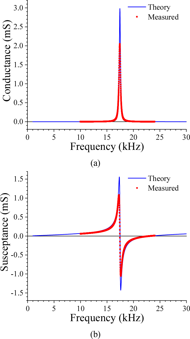
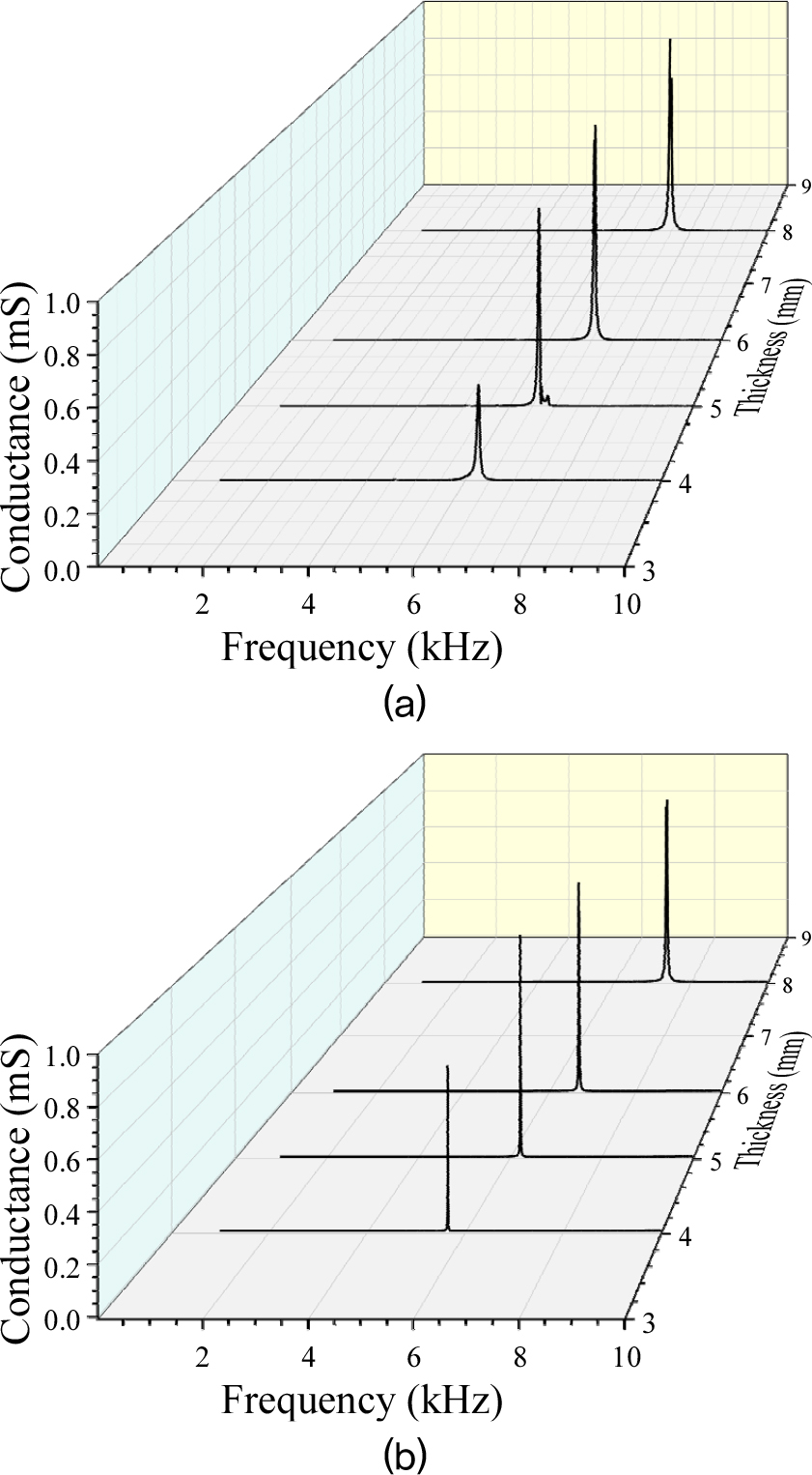
To analyze the characteristics of the piezoelectric stack, the input admittance was measured at the electrical terminal of the piezoelectric stack, as shown in Fig. 5. The results, along with the theoretical calculations, are presented in the figure. The red dots represent the measured values, while the blue line represents the theoretical calculations. A strong agreement between the measured and calculated results can be observed. In the theoretical calculations, the equivalent circuit depicted in Fig. 2 was used, excluding the shell’s mechanical impedance (), with both mechanical terminals of short circuit. The material properties of each piezoelectric element were based on the values listed in Table 1. As shown in the figure, the electrical input admittance was measured after inserting the piezoelectric stack into the elliptical cylindrical shell. The results, illustrated in Fig. 6(a), indicate that as the thickness of the metal shell increases from 4 mm to 8 mm, the resonance frequency of the transducer shifts from approximately 6 kHz to 8 kHz. Corresponding theoretical calculations are presented in Fig. 6(b), which also exhibit a similar trend of resonance frequency shift. It was further observed that the resonance frequency of the system appears in a lower frequency range compared to the resonance frequency of approximately 17 kHz for the piezoelectric stack alone, as shown in Fig. 5. In the theoretical calculations, the input admittance in the electrical terminals of the equivalent circuit was calculated with the shell’s mechanical impedance in both mechanical terminals. The resonance frequency is determined by in Eq. (6), where the terms , and , which form the frequency dependent coefficients , and , have a higher order dependency on the shell thickness . Therefore, as the thickness increases, the mechanical impedance results in a higher resonance frequency.
IV. Conclusions
A mathematical model was proposed for the characteristic analysis of the class IV flextensional transducer, focusing on a simplified structure to investigate how changes in the thickness of its elliptical cylindrical shell affect its resonance characteristics. The analysis showed that as the shell thickness increased from 4.0 mm to 8.0 mm, the resonance frequency rose from approximately 6 kHz to 8 kHz. This indicates that increasing the thickness enhances the shell’s mechanical impedance, leading to a higher resonance frequency. The admittance measurements at the transducer’s electrical input terminal aligned well with theoretical calculations, validating the reliability of the proposed model. This demonstrates its applicability for optimizing shell designs and evaluating new transducer designs. The findings provide a design guide for tuning resonance frequencies by adjusting structural parameters such as shell thickness. These results are significant for optimizing the performance of transducers in applications like underwater acoustic transmitters and broadband receivers.
