

I. Introduction
II. Multichannel delay- compensated FXLMS algorithm
III. Real-time ANC implementation
IV. Experimental Results
V. Conclusions
I. 서 론
ANC (Active Noise Control) cancels the primary noise by generating and combining an anti-noise (with equal amplitude but opposite phase) at the location of the error microphone, and it efficiently attenuates low frequency noise with benefits in size and cost.[1,2] Over the past few decades a great progress has been made in ANC, of which main purpose is generating a quiet zone, where the noise is cancelled. Generally, the quiet zone is generated around the position of error microphone, however, the size of this quiet zone is usually limited especially in a single channel (which means one reference microphone, one cancelling speaker and one error microphone) ANC system.[3] Thus generating a quiet zone with sufficient size and good performance is of considerable significance.

This paper applies a multichannel ANC structure to create a quiet zone with satisfactory size. The multichannel FXLMS algorithm[2] has been widely used for ANC application.[4-6] To improve the performance of quiet zone, a multichannel delay-compensated FXLMS (Filtered-X Least Mean Square) algorithm[7,8] with faster convergence rate and better performance is selected for our multichannel ANC. The proposed multi-channel ANC employes one reference microphone, two cancelling speakers and four error microphones, details on it are discussed in later section. The real-time system is designed and implemented in TMS320C6713 floating-point DSP board, other devices, including microphones and speakers, are connected to DSP board by the self-designed circuit.
The system is tested to cancel 100 to 500 Hz tonal frequency noises generated by a function generator and primary loudspeaker. Experiment results prove that our system generates a quiet zone with sufficient size and maximum 24 dB noise attenuation.
The organization of the paper is as follows: Section II presents the multichannel delay-compensated FXLMS algorithm. Section III describes the real-time system setup and implementation. Section IV illustrates the results the quiet zone. The conclusions are summarized in Section V.
II. Multichannel delay- compensated FXLMS algorithm
FXLMS algorithm has been widely used in practical ANC due to its robustness and simplicity, numerous algorithms are researched to improve its performance, but most of them achieve better performance with a significant computational complexity increase, which cannot be applied for real-time implementation. In the proposed system, a multichannel delay-compensated FXLMS algorithm is applied. It achieves faster convergence rate and better performance with only double computation load, and guarantees the possibility of real-time implementation. The multichannel delay- compensated FXLMS is illustrated in Fig. 1. It employs  reference sensors to form the reference signal vector
  , generates
  cancelling signals
  to drive the corresponding secondary sources, and distributes
  error sensors over desired locations to measure the residual noise components
  .
.
The wide arrows represent an array of signals that are symbolically expressed as vectors. The matrix  represents
  primary path transfer functions,
  , from the reference signal
  to each error sensor output
  . The matrix
  represents
  secondary-path transfer functions,
  , from
  secondary sources to
  error sensors. There are
  possible feedforward channels, each demanding a separate adaptive filter, and these adaptive filters are represented by the matrix
  . The delay-compensated FXLMS algorithm uses the estimated plant models
  to subtract the contribution of the secondary path from the error signals, so that the estimated primary field signals
  are obtained, indeed, the adaptive filters
  then try to predict the estimated signals
  instead of the original
  signals.
Using the following additional notations, we then obtain the multichannel delay-compensated FXLMS algorithm described by Eqs.(1) ~ (5), where  is the length of finite impulse response (FIR) adaptive filters in
  ,
,  is the length of FIR adaptive filters in
  ,
,  is the value at time
  of the
  th cancelling noise signal,
  is the value at time
  of the
  th coefficient in
  ,
,  is the value of the
  th coefficient of
  ,
,  is the value at time
  of the filtered reference signal,
  is the estimate of the value at time
  of the primary sound field
  at the
  th error sensor, and
  is the alternative error signal.
 (1)
(1)
 (2)
(2)
 (3)
(3)
 (4)
(4)
 (5)
(5)
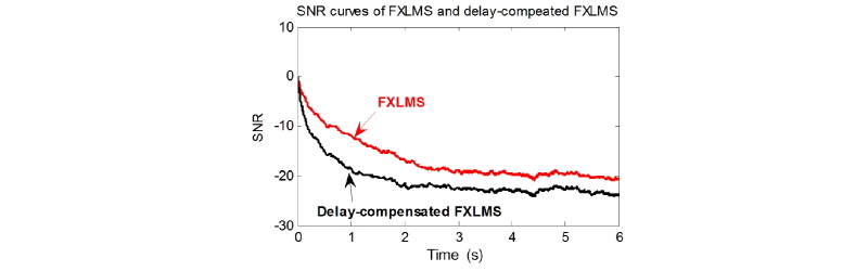
Table 1 presents the number of multiples required for an iteration of both algorithms. Comparing with multichannel FXLMS algorithm, the delay-compensated FXLMS algorithm has almost twice computational load, but much faster convergence speed and better performance (see Fig. 2). 10 fan noises, 10 factory noises and 10 car noises are tested to the performances of two algorithms. The SNR is defined as the ratio between the power of residual noise and power of primary noise. The average SNR curves of 30 simulations are presented in Fig. 2.


III. Real-time ANC implementation
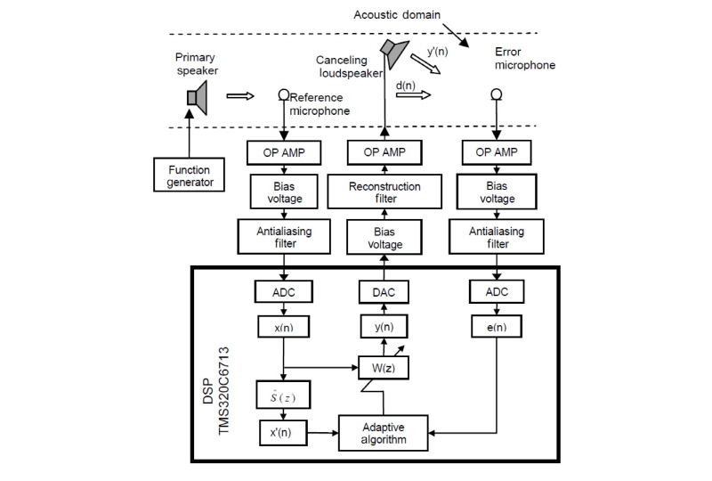
A single channel real-time ANC system[3] is presented in our previous research. It applies one reference microphone, one cancelling speaker, one error microphone and FXLMS algorithm. Its structure is shown in Fig. 3.
The experiment result in the next section proves a quiet zone is generated around the location of error microphone. But it must be noticed that the area of quiet zone is limited, and it is inefficient and meaningless for practical usage. To increase the size of quiet zone, multichannel ANC system with one reference microphone, two cancelling speakers and four error microphones is designed.
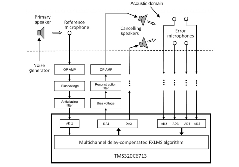
The proposed multichannel system with multichannel delay-compensated FXLMS algorithm is shown in Fig. 4.
The primary noise is generated by function generator and output from a powered studio monitor speaker- YAMAHA HS50, which has a frequency response from 100 to 20 kHz with a maximum power output of 70 W.
The reference microphone and error microphones are unidirectional condenser microphones with 2.2 kΩ impedance, -46±4 dB sensitivity and 70 to 20 kHz frequency response range. The cancelling loudspeakers have the same specifications as the primary loudspeaker.
The system is implemented in TMS320C6713 DSP board, the board employs 12-bit 8-channel A/D convertor AD7888 and 12-bit 4-channel D/A convertor AD7564, both analog input voltage of A/D convertor and analog output voltage of D/A convertor are 0 to 2.5 V. That is the reason we designed +1.25 V bias voltage before the ADC signal input and -1.25 V bias voltage after the DAC signal output. The anti-aliasing filter and reconstruction filter are 4-order low-pass Butterworth filters; their passband frequency is 750 Hz and stopband frequency is set to 1000 Hz with -9 dB stopband attenuation. For the operational amplifier, a balance input microphone amplifier circuit with adjustable gain is designed using high fidelity audio operational amplifier IC LME 49740.
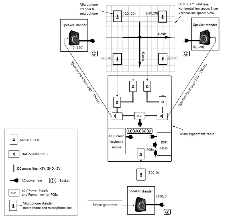
To better understand our system, the equipment setup of multichannel ANC is illustrated in Fig. 5. To simulate the 3 dimensional environment, our system is implemented in a 15×10×3 m room, the heights of microphones and speakers are 1.5 m with their stands.
IV. Experimental Results
|
Fig. 3. The structure of single channel real-time ANC system. |
|
Fig. 4. The structure of proposed multichannel real-time ANC system. |
The real-time ANC system is tested to cancel tonal noises, with frequency range from 100 to 500 Hz, generated by function generator. The system uses 8000 Hz sampling rate, the length of adaptive filter  and
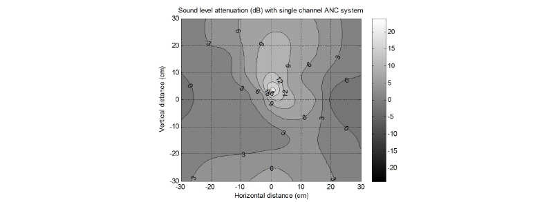
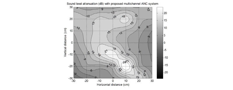
and  are selected as 64 and 128 respectively. A SPL meter is used to measure the quiet zone in terms of noise attenuation (dB). The results are shown in Figs. 6 ~ 8, which present the quiet zone in a 60×60 cm area generated by single channel ANC, multichannel ANC with FXLMS and proposed multichannel ANC with delay- compensated FXLMS.
A coordinate system, as shown in Fig. 5, is to better present the location of equipment. In single channel ANC implementation. The primary noise speaker is placed in (200, 0) (in centimeter), the reference microphone is placed in (150, 0), the cancelling speaker is placed in (40, 40) and error microphone is set at (0, 0). From Fig. 6, a quiet zone with maximum 20 dB attenuation is generated around the location of error microphone. But the area of quiet zone is limited, the quiet zone with 12dB noise attenuation is smaller than a 10×10 cm area, that is inefficient and meaningless for practical usage.
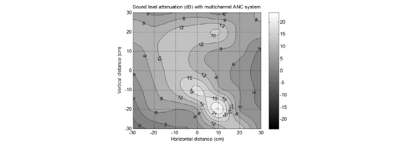
For multichannel ANC systems, the primary noise speaker is placed in (350, 0), the reference microphone is placed in (300, 0), the cancelling speakers are symmetrically placed in (0, -120) and (0, 120), the error microphone are distributed in (20, 20), (-20, 20), (-20, -20) and (20, -20). Comparing the results in Figs. 6 and 7, a multichannel structure successfully enlarges the quiet zone to a satisfactory size. From Figs. 7 and 8, the noise attenuation is evidently improved with multichannel delay-compensated FXLMS algorithm. From Fig. 8, the quiet zone with 12 dB noise attenuation is up to a 40×40 cm area. This proves the quiet zone performance of proposed ANC system is successfully enhanced in both in terms of zone size and noise attenuation.
V. Conclusions
Generating a quiet zone, in which the primary noise is cancelled, is the main objective of ANC. For practical application, this quiet zone must be large enough to satisfy the needs. To enhance the noise cancellation in quiet zone, including enlargement of zone size and improvement of noise cancellation gain, the proposed multichannel real-time ANC system is designed. The proposed system employs multichannel structure, which includes one reference micro-phone, two cancelling speakers and four error microphones, to enlarge the quiet zone; a multichannel delay-compensated FXLMS is then applied to improve the noise attenuation.
The quiet zones generated by ANC system are measured by SPL meter in terms of noise attenuation in dB. The results measured in a 60×60 cm area prove that, comparing with the single channel ANC system and multichannel ANC with FXLMS algorithm, the proposed ANC system successfully enhances the quiet zone performance in terms of zone size and noise attenuation.
