

I. Introduction
II. Optimal design of the sparse array structure
III. Finite element analysis of the sparse arrays
IV. Conclusion
I. Introduction
In recent years, acoustical planar array sensors have found extensive use in underwater applications such as sonar systems and underwater vehicles. The beam pattern of a planar array sensor is a function of its aperture size and is significantly influenced by the number, size, and orientation of the array elements. The cost and complexity of an underwater array sensor is highly dependent on the total number and geometry of the elements.
A fully sampled planar array sensor is a uniform combination of array elements, which may serve as either transmitters or receivers or both at the same time. In principle, the design of an array with periodic element spacing is simple, if the elements are spaced no further than one-half of a wavelength apart.[1] A fully sampled array sensor provides better imaging, yet, it is limited in areas such as high cost and complexity in fabrication. The drawbacks associated with the dense array sensor can be overcome by reducing the number of active elements in the array. A variety of methods has been proposed and employed for the reduction of elements in the dense array including row-column addressing technique,[2] Vernier array,[3] and sparse array techniques.[4]
To overcome the array design limitation in terms of element numbers, the sparse array technique is a promising approach, which can be either periodic or random. In sparse arrays, selection of the best set of active elements demands careful investigation to find the performance level that matches a fully sampled array. Although sparseness simplifies the geometry and operation of an array system, it also leads to energy loss, high side lobe levels, and high grating lobes. The increase in the side lobe level is related to discontinuous apodization, whereas an inter-element distance greater than one half of the wavelength leads to higher grating lobes.[5] The effectiveness of the sparse array in reducing the total number of elements is obvious, but this reduced element array does not result in a performance equal to that obtained when using the fully sampled array. Hence, one should be very careful in determining the structure of the array pattern to ensure that the optimal configuration is reached. Here, the best array pattern means that the least number of active elements are needed to achieve the beam pattern close to that of a fully sampled array.
In this study, the structure of the sparse array is optimized to achieve the performance equivalent to that of the fully sampled array. Optimization of the sparse array is carried out with the objective of keeping its main performance parameters, including the PSLL (Peak Side Lobe Level) and MLBW (Main Lobe Beam Width) within the proximity of the dense array using the OQNLP (OptQuest Nonlinear Programming) algorithm.[6] The validity of the optimized beam patterns is verified by comparing them with those from the FEA (Finite Element Analysis) of the optimized sparse array structure.
II. Optimal design of the sparse array structure
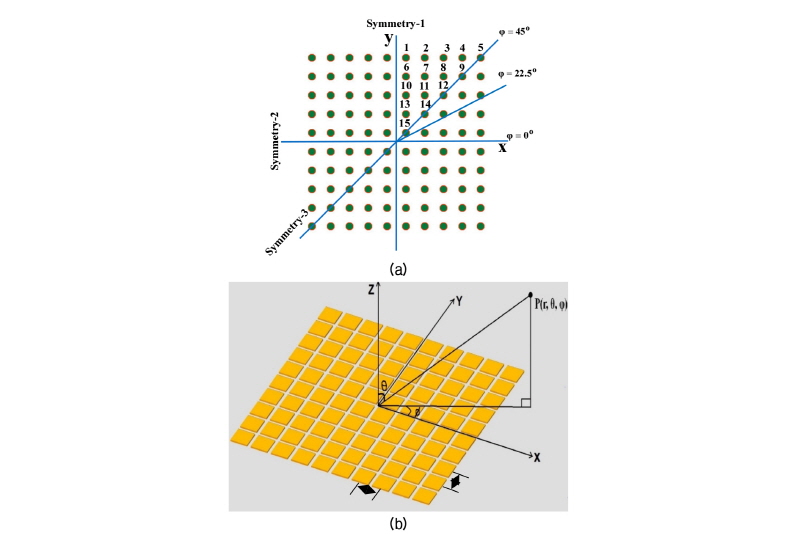
The beam pattern of a fully sampled array is first analyzed as the reference pattern. The beam pattern of a fully sampled array is the pulse echo response of a planar array with uniform elements, which is calculated by multiplying the directional factor of the full array when used as a transmitter and that when used as a receiver. The schematic structure of the fully sampled planar array and coordinate system used to analyze the beam pattern are shown in Fig. 1. The sensor is an M × N array of piston sources, where M and N are 10 in this work. The piston sources are piezoelectric Tonpilz transducers that will be described in the subsequent section. Tonpilz transducers are the most popular type of underwater sensor elements. The effective directional factor, HEffective, of the planar array can be calculated using the product theorem as specified in Eq. (1).[7]
 (1)
(1)
where HE is the directional factor of an individual element like a piston source composing the planar array, HTis the directional factor when the planar array is used as a transmitter with simple sources at the position of each element, and HRis the directional factor when the planar array is used as a receiver with simple sources at the position of each element. The directional factor for a circular piston source is given by Eq. (2).[7]
 (2)
(2)
where J1 is the 1st order Bessel function, k is the wave number, and a is the radius of the piston. Because the underwater array sensor investigated in this work is a piezoelectric sensor, HT and HR are identical owing to the reciprocity of the piezoelectric sensor. The radiation pattern for a planar array of simple sources is computed in a similar manner as described by VanTrees[8] and Lee et al.[9] HT and HRfor a planar array sensor with simple sources of uniform spacing along the X and Y axes are incorporated in Eq. (1). The resultant directional factor of a planar array composed of M × N piston sources is shown in Eq. (3).
 (3)
(3)

where WTmn and WRmn are the elements of the mth row and the nth column of the weighting factor matrices WT and WR for the transmit and receive arrays, respectively, as defined in Eq. (4).
 (4)
(4)
where  = 1 for an active element in the array, and
= 0 for an inactive element in the array.
In Eq. (3), dx and dy represent inter-element spacing along the X and Y axes, respectively. For the fully sampled array, all the elements of WT and WR are 1. For sparse arrays, however, only a portion of them are 1. Using Eq. (3), the beam pattern of a fully sampled 10 × 10 array of piston sources is calculated. This fully sampled array is used as the reference array to be simulated by the sparse arrays. A normalized beam pattern is computed for comparison as stated in Eq. (5).
 . (5)
. (5)
To simplify the calculation, three symmetries are implemented: two symmetries from the square shape of the array layout and the third from the diagonal symmetry as shown in Fig. 1. The quarter array symmetry permits us to use only one-fourth of the array to compute the beam pattern, which can fully portray the 360° directional factor of the array. In addition, diagonal symmetry is induced to keep the beam pattern symmetric even with rotatory movement of the array, which is frequently required for underwater vehicles. All of these symmetries allow the total number of input variables to be reduced to 15, which facilitates the analysis and design of the beam pattern.
The beam pattern of the fully sampled planar array is calculated and presented in Fig. 2. Fig. 2 shows the pulse-echo beam pattern of the planar array when all 100 elements are excited to transmit acoustic waves and, subsequently, the same 100 elements are used to receive the reflected waves. In total, 200 elements are used to obtain the beam pattern.

The purpose of this work is to design a sparse array that has a beam pattern comparable to that of the fully sampled array. In the sparse array, parts of the array elements are used as transmitters and others as receivers, thus reducing the total number of elements to 50 % of the fully sampled array. Reduction of the elements up to 50 % of the fully sampled array is realistic and practical for obtaining good performance without substantial loss of useful energy.[8] The structure of a sparse array is determined by optimizing the number and location of transmitting and receiving elements in the array to make its pulse-echo beam pattern comparable to that in Fig. 2. The primary goal of designing the sparse array is to make its side lobe level as low as that of the fully sampled array. Three azimuth planes are selected for comparison of the PSLL, i.e. 0°, 22.5°, and 45° as shown in Fig. 1. The MLBW of the sparse array is allowed to vary within ± 1° of that of the fully sampled array. The total number of transmitting and receiving elements within the symmetric area in Fig. 1 is 15. The number of active transmitting elements does not need to be the same as that of receiving elements. Each element in the symmetric area should be either a transmitter or a receiver element. The weighting factor of each element (Wmn) is either “1” (active state) or “0” (inactive state) depending on whether the element is used as a transmitter or a receiver. The weighting factor matrix for the transmitter array, WT, is constructed by selecting appropriate elements in the symmetric area. For the receiver array, the weighting factor matrix WR is constructed by combining the remaining elements in the symmetric area. The issue lies in selecting the appropriate elements for WT. Hence, the selection is made through optimization process to satisfy the objection function in Eq. (6).
Objective Function: Minimize the PSLL difference between fully sampled and sparse arrays for three azimuth planes, i.e. 0°, 22.5°, and 45° (6)
Constraints: MLBWfull -1° ≤ MLBWsparse ≤ MLBWfull + 1°,
where MLBWfull is the -6 dB main lobe beam width of the fully sampled array and MLBWsparse is that of a sparse array. The optimization process was carried out using the OQNLP algorithm. OQNLP is a multistart heuristic algo-rithm that finds a global optimum of a constrained nonlinear problem. OQNLP starts with problem initialization that involves definition of the problem parameters such as size, iteration limits, population size, type of variables, and constraints. Then the parameters are updated from iteration to iteration to search a sequence of points that converge to the lowest objective function value. The OQNLP algorithm is estimated to quite effective in searching the global minimum of an objective function even if the objective function is accompanied by many local pitfalls.[6] The elements of the weighting factor matrix were optimized to achieve the objective function as presented in Eq. (6) while satisfying the constraint on the MLBW. The result of the optimization is displayed in Fig. 3 and shows the optimized layout of the sparse array within the symmetric area. The optimized structure contains 5 transmitters and 11 receivers in the symmetric area, which correspond to 32 transmitters and 68 hydrophones in the entire array.

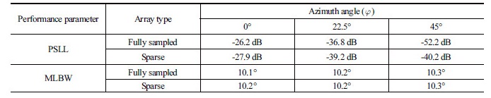
The beam pattern of the sparse array structure is compared with that of the fully sampled array as shown in Fig. 4 for an azimuth angle of f = 0°. A numerical comparison for the three azimuth angles of interest is summarized in Table 1. The sparse array of the optimized structure has a beam pattern very close to that of the fully sampled array in terms of the PSLL and MLBW, satisfying the design objective and constraint. The PSLL of the designed sparse array is even lower than that of the fully sampled array at azimuth angles of 0° and 22.5°. The worst case of side lobe level occurs at the diagonal plane (45° azimuth angle) of the 2D array layout. The PSLL for this azimuth plane is -40.2 dB that is higher than that of the fully sampled array. However, the overall PSLL of both arrays on the 45° azimuth plane is so low that it is almost ignorable in practical use. The sparse array in Fig. 3 has only a half of the elements of the initial fully sampled array, yet it achieved almost the same performance as the fully sampled array. This comparison confirms the effectiveness of the optimal design scheme in this work.

III. Finite element analysis of the sparse arrays
To verify the validity of the analysis and design in the previous section, we carried out FEA of the planar array sensor using a commercial software package, PZFlex®. Taking advantage of the square symmetry of the array utilized for the analytical results, a quarter model of the array was simulated to evaluate the pulse-echo beam pattern of both the sparse and fully sampled arrays at a far-field point. Each element of the array was a Tonpilz transducer that is effective for both transmitting and receiving capabilities.[10] The drive-section material for the Tonpilz transducer used in this study was the piezoelectric single crystal lead magnesium niobate–lead titanate (PMN-PT).[11] Fig. 5 shows an FE model of the Tonpilz element and a quarter model of the planar array comprising the Tonpilz elements.
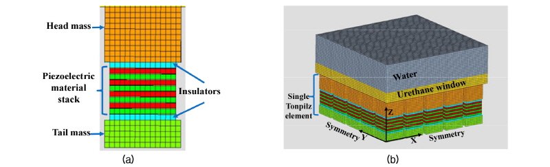
The planar array was modeled to have a center frequency of 100 kHz. The radiating area of each Tonpilz element was 49 mm2, and the inter-element spacing was one half of the wavelength in water, i.e., 7.5 mm. All of the Tonpilz elements of the arrays were attached to a rectangular urethane window of 3 mm thickness to simulate their practical installation condition in water. The top surface of the urethane window was loaded by water. All the outer surfaces of the model were enforced with absorbing boundary conditions to avoid any unwanted reflection of acoustic waves from the boundaries. For the fully sampled array, all the Tonpilz elements were excited together in order for the array to work as a transmitting sensor, and the transmitting beam pattern was acquired. For piezoelectric sensors like the Tonpilz transducers, their receiving beam pattern is the same as the transmitting beam pattern according to the acoustical reciprocity principle.[12] Hence, the effective beam pattern of the fully sampled array was obtained by combining the two beam patterns. A similar procedure was adopted for the optimal sparse array beam pattern. The difference in the sparse array case was the excitation of different active elements for transmitting and receiving of acoustic waves. The resultant beam pattern was then achieved by combining the two beam patterns.
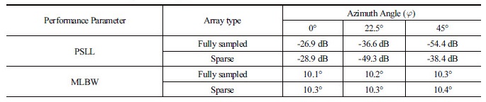
Using FEA, the beam patterns of both the fully sampled and sparse arrays were computed for the three azimuth planes of interest, i.e. 0°, 22.5°, and 45°, as before. Figure 6 is an illustrative comparison of the beam pattern of the optimized sparse array from the FEA with that from the analytical method for the azimuth angle of f = 0°. Detailed numerical values of the two main performance parameters, PSLL and MLBW, are summarized in Table 2 for the three azimuth angles. The FEA results show a good agreement with the analytical results for both the PSLL and MLBW, which verifies the validity of the optimal design results. The slight difference is considered to be due to the presence of crosstalk between the closely stacked elements in the arrays. The FEA could include the effects of this crosstalk but the analytical formulation did not include them, leading to this small difference in values.

IV. Conclusion
In this study, a new design method was presented to optimize the structure of the sparse array to achieve the performance equivalent to that of the fully sampled array for underwater acoustical applications. The fully sampled array was a combination of two square 10 × 10 planar arrays, whose beam pattern was computed using an effective aperture approach to evaluate the main performance parameters, such as PSLL and MLBW. The sparse array designed through structural optimization of the number and location of transmitting and receiving elements in the array was illustrated to have a performance equivalent to that of the fully sampled array, thereby satisfying performance requirements. These results confirmed the effectiveness of the present design method. The validity of the optimized beam patterns was verified by comparing the obtained patterns with those from the FEA of the optimized sparse array structure. The sparse array sensor designed in this work can provide a performance equivalent to that of a fully sampled array while using just half the number of the initial array elements.
