

I. Introduction
II. Backgrounds
2.1 Overview
2.2 Main feature of relay noise
III. Identification of noise attribute
3.1 Reappearance experiments
3.2 Vibration modal analysis
IV. Measures and evaluation for relay’s noise reduction
4.1 Alteration of Movable Contact Structure
4.2 Evaluation of proposed design
V. Conclusions
I. Introduction
Electric Vehicles (EVs) are one of the primary candidates for the next generation of transportation to combat climate change, mainly because they have the advantage of overall energy efficiency and zero emissions compared to the conventional Internal Combustion (IC) engine vehicles.[1,2] Since EVs are powered by high voltage DC power, safety and reliability of the electrical system are required, and as a component of the power system, high voltage DC relays that cut off power from the battery play essential roles. In terms of the operation of electrical systems, the reduction of acoustical noise of electrical components is a challenging issue, and much research work has been done.[3,4,5,6,7,8] This work focuses on the mechanical noise of a DC relay utilized in EVs to control high voltage load and proposes a method to mitigate the noise.
Noises from DC relays can be classified into at least three categories: (1) Impulse noise produced from internal contacts during the switching operation, (2) Noise from structural vibration of relay’s components due to the impact (shock), and (3) High-frequency noise caused by the resonance phenomenon of mechanical components of the relay due to excitation of electromagnetic repulsive force generated around the contact points. The first two types of noises are resolved in various ways, and a few representative research works are introduced. The patent[9] in proposes a way to reduce impact noise by controlling the current of the relay coil to slow the movement of contact points when opening and closing relays. Ko et al.[10] performed a study to improve the impact noise and bounce characteristics between contact points of relays applied to Hybrid Electric Vehicles (HEVs). A study[11] proposes a double-junction spring structure to reduce noise generated when the DC relay is closed. An experimental study[12] has been carried out on noise reduction in relay modules for HEVs, suggesting sealing relay components and insulating vibration to battery packs. However, much research has not been reported for the vibration and noise reduction issues on the third type of noise listed above. Given these circumstances, this work analyzes the causes of high- frequency noise generated by the contacts’ vibration and proposes a contact structure to reduce this noise. In the following, the detail of the analysis and the proposed method is illustrated. In order to proceed, this paper is organized as follows. In Section 2, the structure of the DC relay at hand is given. The overall noise level of the DC relay equipped in EVs is introduced with and without acceleration operation of the vehicle. In Section 3, noise characteristics of the DC relay are identified through reappearance tests and vibration mode analysis. A noise reduction method is proposed, and its performance evaluation is discussed in Section 4. Finally, Section 5 concludes the paper with a summary of the work.
II. Backgrounds
2.1 Overview
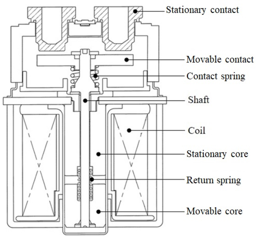
The DC relay considered in this work is employed in EVs, consisting of a stationary contact, a movable contact, a shaft, contact and return springs, and electrical actuators that can operate on control signals (see Fig. 1). Refer to Gurevich's book for electric relays for more details.[13] The stationary and movable contacts of the DC relay act as the bridge through which the electric power from the battery is supplied to electric components. The current flow at the contacts is directly related to EVs’ acceleration performance characteristics, which affect the motor’s output torque, so does the change of the battery’s voltage. In this work, although the first two types of noise introduced above are also an important consideration, it is intended to address high-frequency sound associated with vibration caused by electromagnetic forces due to current flowing when the relay is working.
2.2 Main feature of relay noise
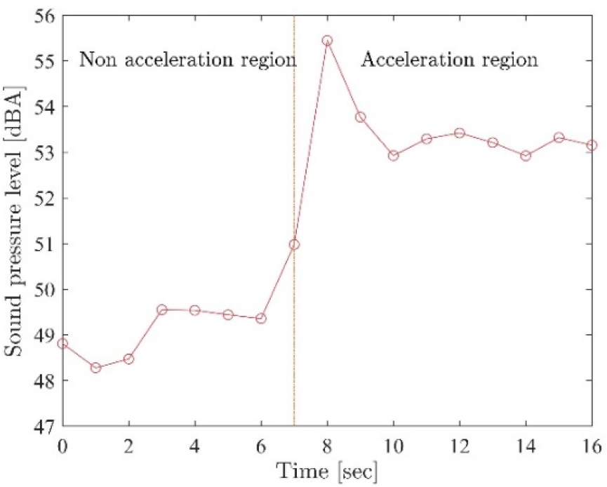
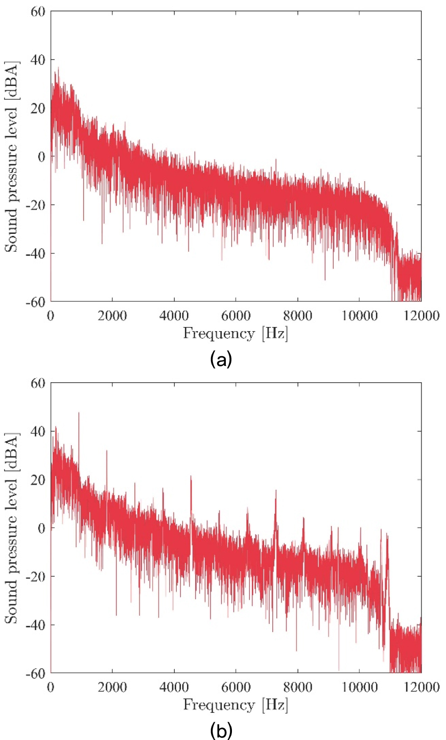
Fig. 2 indicates the measurement of sound produced by a DC relay mounted on the vehicle under development during operation. Noise in the acceleration region is more extensive than in the non-acceleration region, mainly due to increased electric motor input. It can be seen from Fig. 3 that the noise characteristics of the acceleration region not only have a specific high-frequency band but also occur in the form of harmonics, unlike the non-acceleration region.
III. Identification of noise attribute
3.1 Reappearance experiments
A set of reappearance experiments have been conducted to investigate the characteristics of relay's sound at the laboratory level. Since the DC relay equipped in the vehicle at a developmental stage shows a high-frequency sound when the current flows in the normally closed state, 150 amps of current from DC and AC power sources each was allowed to flow for 20 seconds through the contact points of the relay and measured the sound pressure level using a microphone. For the AC power application, the current with different frequencies was applied to prevent harmonics from overlapping as much as possible, as shown in Table 1. Fig. 4 is the result from the reappearance experiments.
Table 1.
Electric current sources for reappearance tests.
| Source | Frequency (Hz) |
| DC 150A | -- |
| AC 150A | 120 |
| 140 | |
| 150 |
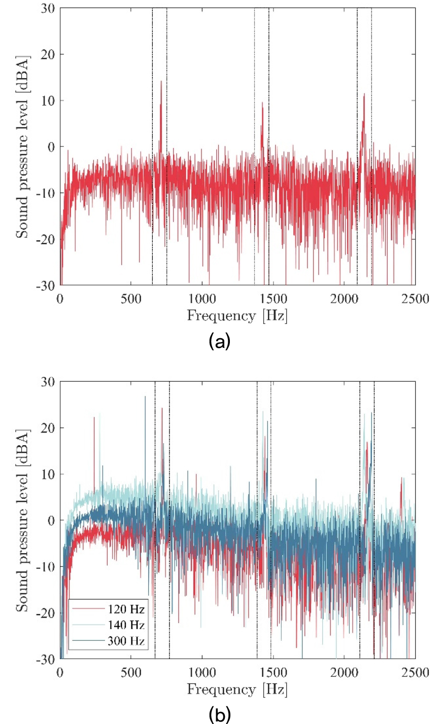
It is observed from the Fig. that sound with a specific frequency range (710 Hz ~ 730 Hz) occurs in common regardless of the types of power. In particular, in the AC power application, the sound with the multiple frequency components of the fundamental frequency of currents each is generated. Furthermore, it is observed that the sound of a particular frequency, which is not related to the multiple frequency components of each fundamental frequency of current applied, is commonly produced. It is speculated that this frequency is related to the resonant frequency of certain parts within the DC relay. The resonance is caused by the presence of external forces with a component of the resonance frequencies. The external force exerted on the DC relay can be originated from the electric current going through the contact spots. The generation of electromagnetic force at the contacts can be illustrated by the Holm’s a-spot model given in Fig. 5.[14,15,16,17]
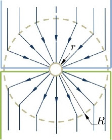
In terms of the direction of an electric current around the contact, the current is directed toward the center of the contact in the upper side of contact (i.e., stationary contact) and vice versa at the lower side of contact (i.e., movable contact). Current passing across a contact interface is constricted to flow through a-spots.[18]
The electromagnetic repulsive force F can be represented from Holm's equation shown in the below[14,18]
where μ is the permeability (4π × 10-7 [N/A2] for air), I represents the electric current [A], R the equivalent radius of the area of contact and r the radius of contact spot [mm].
3.2 Vibration modal analysis
Since it is expected that the resonance phenomenon of specific parts inside the DC relay cause noise generation, vibration mode analyses on the relay have been performed by constructing FE models of the relay.
A commercial 3D designing program was used, and its FE model was established. The FE model consists of the stationary and movable contacts and the contact spring shown in Fig. 6. The 10-node tetrahedron with mid-node was used as a finite element. In the two (three)-point contact model, the total number of nodes and finite elements is shown in the Table 2. The boundary conditions of the contact points in the FE model have been set as a “bonded condition” so that the lower nodes of the movable contact and the upper ones of the contact spring are not separated. Table 3 lists the material properties used in the relay model.
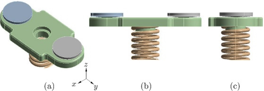
Table 2.
The number of nodes and finite elements in FE models. Note. SC/MC, Stationary/Movable contact; CS, Contact spring.
| Model | Part | Number of nodes | Number of elements |
|
Two-point contact | SC | 5364 | 2968 |
| MC | 22919 | 14504 | |
| CS | 4399 | 1679 | |
| Three-point contact | SC | 5434 | 3030 |
| MC | 22024 | 14006 | |
| CS | 4347 | 1657 |
Table 3.
Material properties assigned in FE models.
| Part | Material |
Density (kg/mm3) |
Young’s Modulus (MPa) |
Poisson’s Ratio (-) |
| SC | Copper Alloy | 8.30e-6 | 110,000 | 0.34 |
| MC | Copper Alloy | 8.30e-6 | 110,000 | 0.34 |
| CS | Steel | 7.85e-6 | 200,000 | 0.30 |
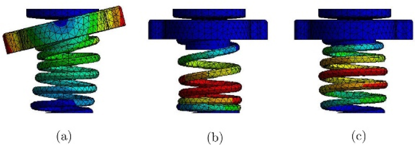
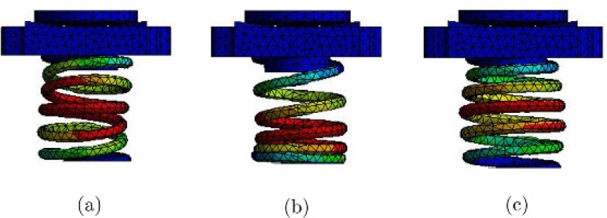
With the FE model established, a vibration mode analysis was conducted up to the third mode, and its natural frequency and mode shape per mode are given in Fig. 7. The first mode showed that at the frequency of 722 Hz, the movable contact rotates about the y-axis (see Fig. 6 for the axis of direction), while the movable contact is in contact with the stationary contact by the elastic force of the contact spring. The second and third modes exist above the frequency of 2,000 Hz and represent the rotational and translational motion modes of the contact spring itself. It can be seen that the frequency of the first mode is similar to the frequency of the noise identified in the experiment.
IV. Measures and evaluation for relay’s noise reduction
4.1 Alteration of Movable Contact Structure
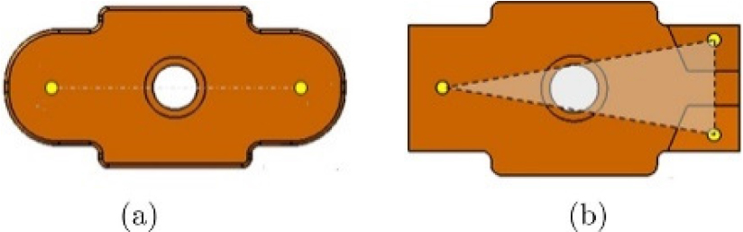
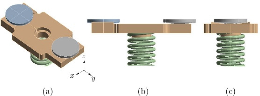
The previous section observed that the movable contact rotates while contacting the stationary contact in the first resonance mode. As shown in Fig. 8(a), the contacts take place at two points, and the movable contact rotates around the virtual line connecting these points. This aspect appears in the first vibration mode. Therefore, it is necessary to constrain the degree of freedom of rotation of the movable contact to remove the first rotational vibration mode. One way to constrain the rotational motion is to create not a line but a plane when contact points are connected to each other. The minimum number of contact points required to make a plane is three. Based on the discussion above, a structural and straightforward design is proposed to prevent the rotation of the movable contacts (and to reduce high-frequency relay’s noise finally), which changes the movable contact's shape so that one end of the movable contact comes into contact with the stationary contact at two points, as shown in Fig. 8(b).
4.2 Evaluation of proposed design
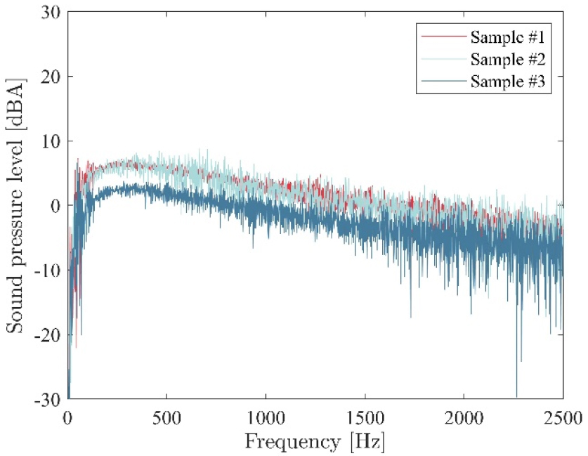
Fig. 9 shows an FE model for the relay with the proposed structure in Fig. 8(b). Like the existing two-point contact structure, the FE model consists of the stationary contact, the movable contact, and the contact spring. With the FE model established, a vibration mode analysis has been conducted up to the third mode, and its natural frequency and mode shape per mode is given in Fig. 10. According to the modal analysis results of the structure shown in Fig. 9, unlike the conventional two-point contact structure, the rotation mode shown in the two-point contact structure disappears. Furthermore, the second and third modes in the two-point contact structure again appear in order. Twenty DC relays applied with the proposed design were fabricated, and a set of tests were conducted to verify its applicability using a DC power source (discussed in Section 3). Fig. 11 shows the noise frequency spectrum resulting from the tests. As shown in the Fig., for the three samples randomly selected among 20, we observe that high-frequency noise disappears compared with the existing two-point contact structure.
V. Conclusions
In this work, a structural and straightforward design is proposed to reduce the high-frequency sound emitted from a DC relay during operation. The characteristics of high-frequency sound were investigated via the actual driving and laboratory level tests. It is found from the investigation that the noise is caused by the forced vibration of the relay's components, which are exerted by the electromagnetic repulsive force. The repulsive force at hand is one generated at the electric contacts through which electric power is flowing. FE models, including electric contacts (the stationary and movable contacts) and the contact spring, are established to conduct vibration mode analyses. Through vibration mode analyses, an alteration of the movable contact structure is proposed, and its prototype relays applied with the proposed design are fabricated. Vibration reduction capability was evaluated for the relays with the proposed design through transmitting DC power to the relay and measuring its sound pressure level. Evaluation results say that the vibration at 722 Hz generated from the existing relay with the two- point contact structure disappears. From the observation, one can conclude that the proposed design gives one of the simple but viable solutions to reduce the relay’s high- frequency noise.
