

I. Introduction
II. Characterization of the refractory brick
III. Modal analysis using FEA
IV. Measurement of refractory brick thickness using impact-echo technique
V. Conclusions
I. Introduction
A blast furnace covered by steel plates on its outer side and by a refractory lining on its inner side is used to obtain pig iron from iron ore. The refractory lining is a wall of refractory bricks that can withstand elevated temperatures as high as 1600 °C. It plays an important role in protecting the metallic structure of the blast furnace at elevated tempera-tures and maintaining the initial geometric configuration of the furnace for an extended time.[1] Although the refractory lining has high thermal resistance, it is inevitable for the lining to suffer from the degradation of its thickness and properties when the furnace is operated over a long period. Therefore, to increase the lifetime of the furnace, timely detection of severe degradation and replacement of eroded areas with new refractory bricks is mandatory.[2] To replace the refractory bricks, the operation of the blast furnace should be stopped. However, the shutdown cost is very high for a large blast furnace; hence, the replacement should be conducted after examination of the exact state of degradation. Therefore, studies using NDT (Non-Destructive Testing) techniques are being carried out to resolve this pro-blem; an accurate measurement of the remaining thickness of a refractory lining is carried out.[3]
The acoustic NDT techniques available for the charac-terization of refractory ceramics include the impact-echo technique,[4,5] acoustic emission technique,[6] and ultrasonic pulse-echo technique. In this work, the impact-echo techni-que is used to characterize the state of refractory ceramics in a blast furnace. The impact-echo technique was developed by Carino and Sansalone to inspect flaws in concrete or masonry.[7] Nowadays, this technique is used not only for concrete specimen inspection[8,9] but also for concrete slab inspection,[10-14] inspection of the grouting in a tunnel lining,[15] concrete pavement thickness inspection,[16,17] bridge defeat inspection,[18,19] and so on. In case of refractory ceramics, there is considerable variation in the composition of constituent materials as they are produced by many different manufacturers.[20,21] Hence, the impact-echo technique should be well refined to reflect the properties of particular refractories for accurate characterization of their state.
To measure the thickness of a refractory lining using the impact-echo technique, the vibration characteristics of the refractory ceramic (used in the blast furnace) should be identified first.[22,23] In general, the vibration characteristics of refractory ceramics are identified by assuming the ceramics as isotropic materials. However, in practice, refractory ceramics exhibit anisotropic properties as they are manufactured by pressing ceramic powder along a particular direction. In this research, the frequency responses of refractory ceramic bricks along the width, length, and height directions are acquired by considering tetragonal symmetry in the material properties of the refractory ceramics.
In case of concrete, its longitudinal wave velocity is already known from several previous studies.[7] However, in case of refractory ceramics, no general acoustic properties are available, so it is necessary to determine the longitudi-nal wave velocities properties of a specific refractory sample of interest. Therefore, in this work, the longitudinal wave velocities of a refractory brick were measured along different crystal directions using the ultrasonic through-transmission technique. The vibration characteristics of refractory bricks were then examined by using FEA (Finite Element Analysis). The refractory bricks were considered to have tetragonal crystal symmetry in their material properties. With respect to the anisotropic properties, the frequency of the fundamental vibration mode along each crystal direction was acquired, which led to the estimation of the thickness of the brick along each direction. The validity of the estimated thicknesses using FEA was verified by comparing them with experimentally measured values.
II. Characterization of the refractory brick
The refractory brick characterized in this work is a standard carbon block (Nippon Electrode Company Ltd. Grade BC-5) whose density is 1,920 kg/m3. The impact-echo technique allows the measurement of the thickness of the brick based on the principle presented in Eq. (1).[7,24,25]
 , (1)
, (1)
where f, T, and V are frequency of the fundamental vibration mode, thickness, and sound velocity of the brick, respectively. As stated in Eq. (1), it is necessary to know the sound velocity beforehand to estimate the thickness of a refractory brick using the impact-echo technique. Hence, the longitudinal and shear wave velocities of the refractory brick were measured. The dimension of the brick used for the sound velocity measurement was 150 mm (width) × 400 mm (length) × 300 mm (height). In manufacturing the brick, pressure was applied along the height direction. The width, length, and height were marked as X, Y, and Z, respectively.
The sound velocities along the three directions were measured using the ultrasonic through-transmission technique. The instruments used were a pulser/receiver (Olympus Panametrics 5072PR), an oscilloscope (LeCroy LT322), and ultrasonic transducers (Olympus Panametrics NDT V103 and V153). The measurement was conducted by attaching a transmitting transducer and receiving transducer on the opposite planes of an aluminum plate that has dimensions of 300 mm (width) × 270 mm (length) × 20 mm (height), as shown in Fig. 1(a). The flight time t1 of the first peak of an ultrasound wave was measured. The same aluminum plate was then attached along the measure-ment direction of the refractory material. The transmitting and receiving transducers were placed at the central points of two opposite planes as illustrated in Fig. 1(b), and the flight time t2 of the first peak of the same ultrasound wave was measured. An acoustic coupling gel was used to attach the aluminum plate to the refractory material for transmission of the ultrasonic pulse wave. The difference (∆t) between t1 and t2 in Fig. 2 for each direction along the brick was the flight time taken by the ultrasonic pulse wave to propagate inside the refractory brick. The sound velocity along each direction was calculated using the flight time (∆t) and thickness in that direction.


As refractory bricks are manufactured by pressing ceramic powders along one particular direction, the bricks have anisotropic properties. The refractory brick in this work was pressed along the Z direction. Thus, the sound velocity along the Z direction was likely to be different from that along the other two directions. In the experiment, the longitudinal wave velocities V11, V22, and V33 along the X, Y, and Z directions were measured to be 2981, 2954, and 2662 m/s, respectively. The shear wave velocities V44, V55, and V66 on the YZ, XZ, and XY planes were 1796, 1801, and 1903 m/s, respectively. It was confirmed that the sound velocity along the X and Y directions was almost the same whereas that along the Z direction was lower. From these results, it was confirmed that the refractory brick possessed anisotropic properties. Therefore, all the anisot-ropic properties of the brick were identified. The refractory brick was transversely isotropic along the Z direction. This implies that the longitudinal wave velocities along the X and Y directions were identical, and the brick was considered to have a tetragonal 4 mm structural symmetry.[26] The validity of this assumption was verified through FEA of the brick, which is presented in the next section.
Materials having tetragonal 4 mm structural symmetry have six independent constants in their elastic stiffness matrix.[26,27] The elastic stiffness constants could be deter-mined from the measured sound velocities using Eq. (2). The average of the longitudinal wave velocities V11 and V22 was used to calculate C11, while V33 was used to calculate C33. For the shear terms, the average of the shear wave velocities V44 and V55 was used to calculate C44, while V66 was used to calculate C66. The remaining constants C12 and C13 were calculated using Eqs. (3) and (4). These two equations were derived by simulating the tetragonal brick as a general, transversely isotropic material, like that having hexagonal symmetry.[27]
 , (2)
, (2)
 , (3)
, (3)
 , (4)
, (4)
where  is the density. Once these six independent constants were found, the other nonzero constants in the stiffness matrix could be derived from these constants; C22 = C11, C55 = C44, and C13 = C23. Through this process, all the stiffness constants could be determined, and Fig. 3 shows the resultant stiffness matrix.

III. Modal analysis using FEA
After obtaining the anisotropic elastic stiffness matrix, a numerical modal analysis was conducted using the commercial FEA package PZFlex® to analyze the vibrational characteristics of the refractory brick, such as resonance frequencies and mode shapes.[28]
Harmonic analysis using the PZFlex® is described as follows: An impulse with the waveform of a half- period sine wave was applied to the center of a vertical plane of the refractory brick, and the displacement occurring at the opposite plane was analyzed. No boundary constraint was imposed. The impulse response occurring from the opposite plane was transformed to a frequency response, and the fundamental vibration mode frequencies along the three directions were identified. The dimensions of the brick used for numerical analysis were 200 mm (width) × 400 mm (length) × 150 mm (height). Fig. 4 shows the frequency response along the Y direction as a representa-tive result, which was normalized with respect to the maximum peak value and is presented on the dB scale.

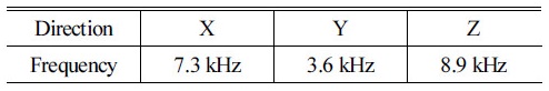
The fundamental vibration mode frequencies acquired from the modal analysis are presented in Table 1. The fundamental mode frequencies can also be obtained from Eq. (1) using the measured longitudinal wave velocities; they are 7.4, 3.7, and 8.9 kHz along the X, Y, and Z directions, respectively. The fundamental mode frequencies acquired from the modal analysis and those from Eq. (1) are in close agreement.
IV. Measurement of refractory brick thickness using impact-echo technique
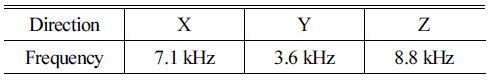
The frequency response of a refractory brick that has the same dimensions as that used in the numerical analysis was measured experimentally using the impact-echo technique. The instruments used in the experiment were an impact hammer (PCB Piezotronics 208A02), accelerometer (B&K 4367), and amplifier (Type 2692 by Bruel & Kjaer). The center of a vertical plane of the refractory brick was hit by the impact hammer, and the response at the opposite plane was measured by the accelerometer. The acceleration response was converted to the corresponding displacement response to match the results of the modal analysis in the previous section. As a representative case, Fig. 5 shows the location of the impact point and the frequency response along the Y direction. The frequency response is normalized with respect to the maximum peak value and is presented on the dB scale. The experimentally obtained frequency of the fundamental vibration mode in that direction is marked in the figure. Similar experimental frequency response analyses were conducted for the other directions as well, and their results are summarized in Table 2. The experiment-ally identified natural frequencies of the fundamental vibration mode agree very well with those obtained from the numerical modal analysis, which confirms the validity of the experiments and the natural frequencies. This good agreement was possible because the modal analysis incor-porated the exact anisotropic properties of the refractory brick.

Table 2. Fundamental mode frequencies identified from impact-echo measurements of the refractory brick.
 |
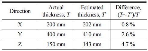
Once the natural frequency of the fundamental mode along a particular direction is identified, the thickness of the refractory brick along that direction can be determined using Eq. (1). The thicknesses of the refractory brick along the X, Y, and Z directions were estimated in this manner, and the results are summarized in Table 3. As noted in Table 3, the estimated thicknesses differ from the actual thicknesses by 4.7 % at the most. According to previous studies, this extent of agreement has not been possible because all the previous studies have assumed that the refractory material has isotropic properties.[4,5] Therefore, it was concluded that we could accurately estimate the thickness of a refractory brick using the impact-echo technique with measurement errors not exceeding 4.7 %. However, the measurement error in the Z direction is considerably high when compared with that in the X and Y directions. The probable reason is that the material properties of the brick in the Z direction are inhomogeneous because of the pressing during the manufacturing process.
V. Conclusions
In this research, the vibration characteristics of the refractory brick were analyzed by considering the anisotropic properties of the material. The refractory brick was considered to have tetragonal structural symmetry. Accurate characterization of the anisotropic properties of the refractory brick led to a close agreement between the results from the numerical modal analysis and experimental measurements; such agreement was not possible in previous-ly reported studies. Based on the vibration characteristics, the thicknesses of the refractory brick were estimated along the X, Y, and Z directions. The estimated thicknesses differed from the actual thicknesses by less than 5 %. This confirms the effectiveness of the impact-echo technique along with anisotropic property characterization to evaluate the thickness of the refractory brick. The procedure adopted in this study can be conveniently applied to the thickness estimation of other ceramic materials as well as isotropic materials.
