

I. Introduction
In the field of sonochemistry, which utilizes ultrasound to promote chemical reactions or induce changes in physical properties, it is common practice to avoid direct contact between the radiating surface of the ultrasonic transducer and the liquid sample to maintain sample purity.[1,2] To achieve this, samples contained in glass vessels receive ultrasonic energy through an acoustic transmission medium, typically water.[3,4] When high-intensity ultrasonic energy is required, it is customary for the ultrasonic energy to be transmitted through the side of the cylindrical container holding the sample in order to focus the energy.[5,6] The plane waves emitted from the ultrasonic transducer reflect and transmit through the sides of the cylindrical container, creating an acoustic field inside the container. The distribution of this acoustic field depends on the thickness of the cylindrical container. Theoretical analyses of the transmission and scattering of plane ultrasonic waves by cylindrical containers have been widely reported.[7,8,9] However, these studies often focus on cylindrical shells or employ highly complex mathematical expressions that consider transverse waves within the material of the cylindrical container, which are practically insignificant. In this study, a relatively simple mathematical analysis model was proposed for practical applications, and its validity was verified by comparing it with experimental results for cylindrical containers of varying thicknesses.
II. Calculation model
As shown in Fig. 1, the external and internal regions of the cylindrical container are denoted as I and III, respectively, while the medium constituting the cylindrical container is denoted as II. The sound speeds in each medium are denoted as , and , and the densities are denoted as , and , respectively.
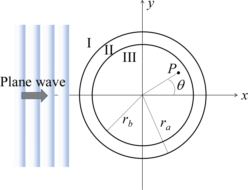
Assuming the length of the cylinder is infinite and that there is no variation in the incident sound pressure along the direction of the length, the wave equation in cylindrical coordinates for each region can be expressed as follows.
Here, is the sound speed in each region. The solutions for the incident sound pressure and scattered sound pressure in each region can be obtained as follows.
Here, the subscripts in and sc indicate the incident wave and scattered wave, respectively, while the subscripts 1, 2, and 3 represent each region. Additionally, , , , , and represent the pressure amplitude of the incident wave, the Neumann coefficient (=1, =2),[10] the distance from the origin, the amplitude coefficient of the scattered wave, and the wave number in each region, respectively. The transverse wave that could occur in the solid cylindrical medium is neglected in this analysis. On the other hand, the particle velocity is defined as follows.
The particle velocity in each region can be determined as follows.
By applying the conditions of continuity for sound pressure and particle velocity at each boundary, the following results are obtained.
At =0, the particle velocity must have a finite value. Therefore, the following expression must not diverge.
By applying Eqs. (2) to (7) and (9) to (14) to Eqs. (15) to (18) and combining the results with Eq. (19), they can be expressed in matrix form as follows.
Here,
,
, , , , , , , ,
, , ,
,, , ,
, , .
From Eqs. (6) and (7), the acoustic field distribution inside the solid cylindrical tube can be expressed as follows.
Therefore, by substituting the amplitude coefficients and obtained from Eq. (20) into (21), the acoustic field distribution inside the solid cylindrical tube can be determined.
III. Experiment method
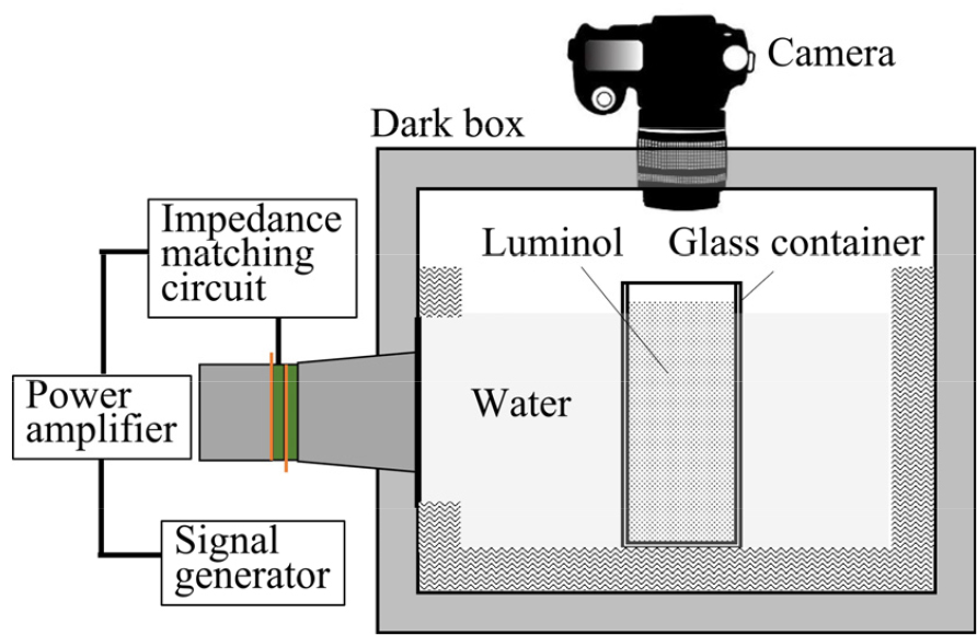
As shown in Fig. 2, the experiment used a 300 mm × 300 mm × 300 mm acrylic tank with a 10 mm thickness, lined with sound-absorbing material on the inner walls and bottom. A Langevin-type ultrasonic transducer with a resonance frequency of 40 kHz was fixed to one side of the tank to emit plane waves. A glass cylindrical container with an outer radius of 25 mm was used as the cylindrical container. It was positioned in front of the radiating surface of the transducer so that sound waves were incident on its side. The cylindrical container was filled with a luminol solution, while the rest of the tank, excluding the container, was filled with distilled water. All outer walls of the tank were covered with blackout material to block light transmission, except for the top surface, which had a hole to allow a camera to capture luminol luminescence images generated inside the cylindrical container. To investigate the distribution of the transmitted sound field with varying thicknesses of the cylindrical container, measurements were conducted by changing the thickness of the glass container to 1.2 mm, 1.8 mm, and 3.2 mm.
IV. Results
Fig. 3 shows the calculation results of acoustic pressure distribution in the cylindrical container with varying thicknesses. The results in Fig. 3, represented as a density plot, show the case where a plane wave is incident from the left to the right. In Fig. 3(a), the results correspond to the case where the cylindrical container has a thickness of 1.2 mm. The sound pressure distribution inside the cylinder exhibits a curved planar wave pattern, and it can be observed that the region opposite to the side of the incident plane wave exhibits a higher sound pressure level. In Fig. 3(b), which represents the results for a slightly thicker cylindrical container with a thickness of 1.8 mm, the sound pressure near the center of the cylinder appears slightly lower compared to that of Fig. 3(a). This is believed to be due to changes in the interference patterns of the scattered waves caused by the reduced inner diameter of the cylindrical container. Fig. 3(c) shows the results for a case where the thickness of the cylinder is further increased to 3.2 mm. Due to scattering and interference, the sound pressure near the center of the cylinder is observed to be even lower. The 3D graph on the left indicates that, for the thinnest case shown in Fig. 3(a), the sound pressure level is actually lower compared to the other cases. This suggests the existence of an optimal glass cylinder thickness where the transmission coefficient is maximized relative to the wavelength of the incident plane wave. Fig. 4 shows the experimental results.
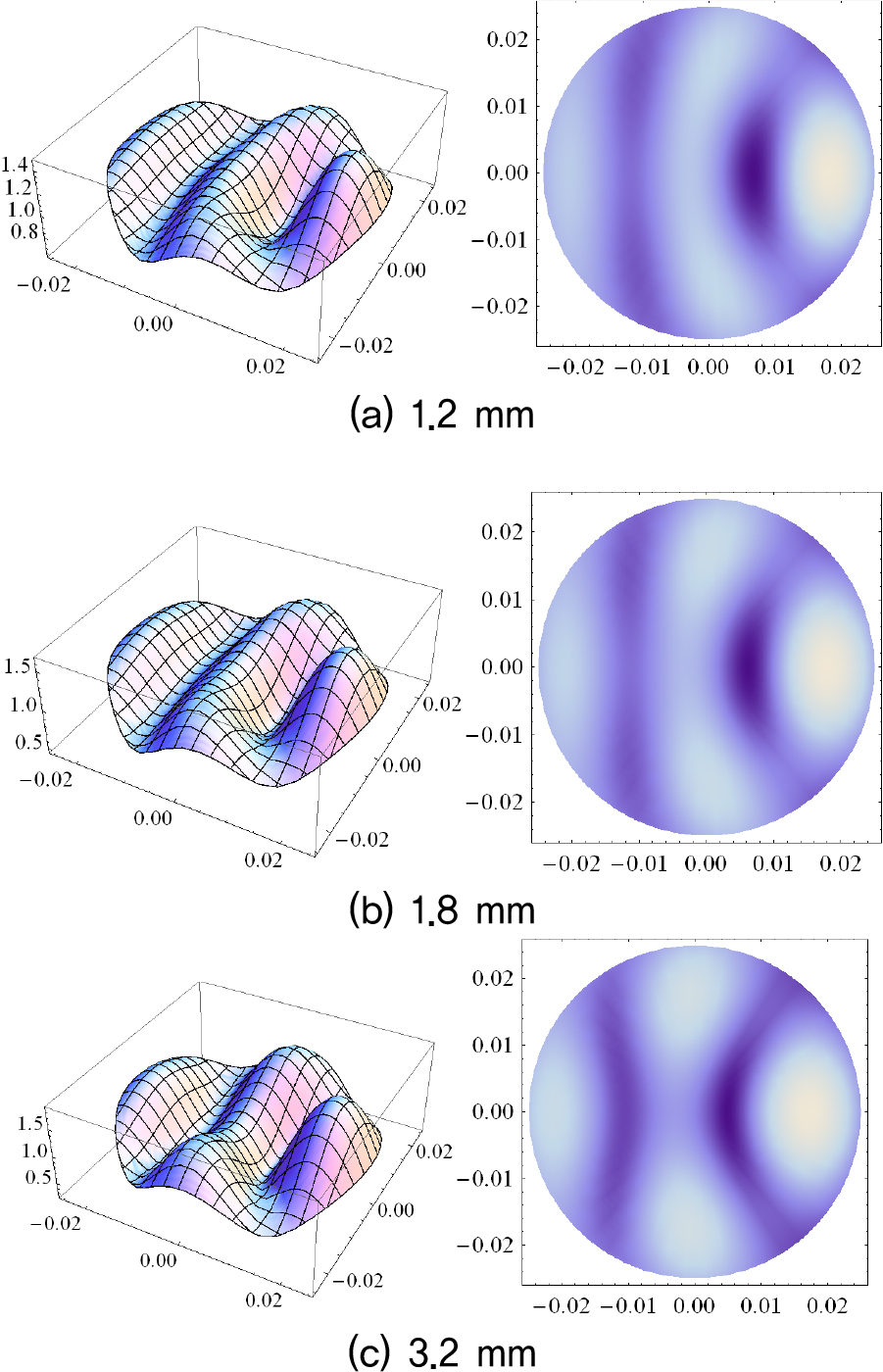
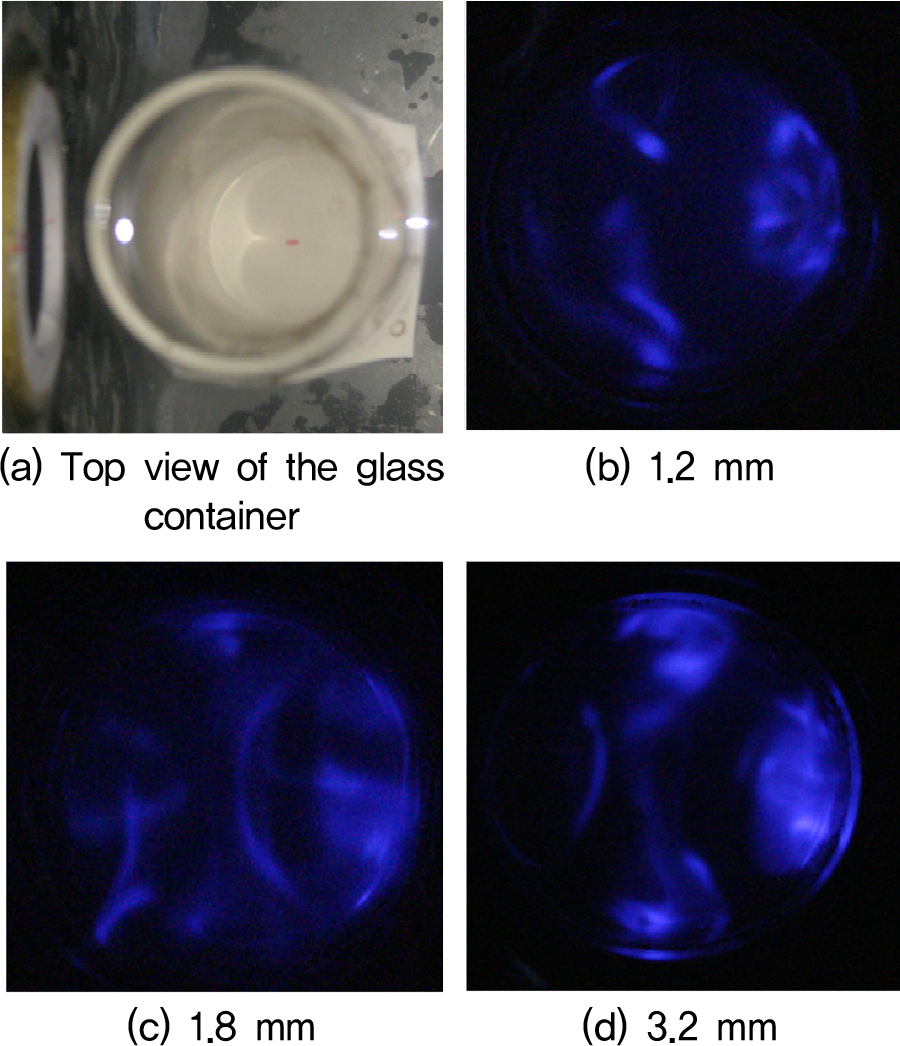
Fig. 4(a) is a photograph depicting the glass cylindrical container fixed inside the water tank and the radiating surface of the transducer. The distance between the center of the glass cylinder and the radiating surface of the transducer was 30 mm. The luminescence images of the luminol solution filled inside the glass cylinder are shown in Fig. 4(b) ~ (d). Fig. 4(a) illustrates the luminescence pattern induced by the ultrasound transmitted through the glass cylinder with a thickness of 1.2 mm. This result closely resembles the theoretical calculation shown in Fig. 3(a), demonstrating the characteristic appearance of a plane wave. This is attributed to the relatively thin wall of the glass cylinder, which results in minimal internal scattering of the acoustic waves within the glass medium. The experimental result for the case where the glass cylinder has a thickness of 1.8 mm is shown in Fig. 4(b). Compared to the result in Fig. 4(a), the acoustic pressure distribution in this case appears more curved. Fig. 4(d) shows the luminescence pattern of luminol for the glass cylinder with a thickness of 3.2 mm. This result closely matches the theoretical calculation shown in Fig. 3(c). The ultrasound transmitted and scattered inside the glass cylinder exhibits a lower acoustic pressure at the center of the cylinder due to interference, while a higher acoustic pressure distribution is observed on the wall opposite the direction of incidence. This acoustic pressure distribution aligns well with the theoretical calculation results.
V. Conclusion
This study verified the theoretical model for predicting the distribution of acoustic fields inside a solid cylindrical vessel when ultrasound is transmitted from the outside, with a particular focus on the effect of material thickness on ultrasound transmission characteristics.
Experimentally, luminol luminescence patterns were used to compare theoretical predictions with observed phenomena, confirming that the cylinder thickness plays a crucial role in shaping the acoustic field distribution.
A thin cylinder (1.2 mm) exhibited a planar wave pattern with minimal internal scattering, closely matching theoretical calculations. As the cylinder thickness increased (1.8 mm and 3.2 mm), the acoustic pressure distribution became more curved, attributed to enhanced scattering and interference effects. For thicker cylinders, the ultrasound waves transmitted and scattered inside exhibited reduced acoustic pressure at the center and higher pressure along the walls opposite the incident direction, which aligned well with theoretical calculations.
These findings emphasize the critical role of scattering and interference in acoustic field formation and suggest the existence of an optimal cylinder thickness that maximizes ultrasound transmission efficiency relative to its wavelength.
By combining theoretical predictions with experimental validation, this study establishes a quantitative foundation for analyzing ultrasound transmission characteristics. The results provide valuable insights for applications such as sonochemistry, medical ultrasonics, and material processing, where precise control of ultrasound transmission is essential. Additionally, the practical calculation model proposed in this study serves as an accessible tool for researchers and engineers, bridging the gap between theoretical complexity and real-world implementation.
Future studies will investigate the distribution of internal acoustic fields in containers of various shapes and materials to evaluate the applicability of this theory. This will help assess the model’s validity and expand its potential use in ultrasonic applications.
