

I. Introduction
The behavior of strings has been studied and simulated in various ways. Based on the fact that oppositely travelling waves exist on each of a string and an electrical transmission line, the vibrating string was considered as the transmission line in continuous time domain.[1-3] The string was modeled in discrete time domain. The representative is known as the structure of the Karplus-Strong algorithm consisting of a delay line followed by a filter in a loop, and the filter was later modified to accomplish the frequency- dependent damping of harmonics.[4,5] The other structure in discrete time domain was built in the form of digital waveguides in which two delay lines carry sampled travelling waves.[6] As a numerical approach, the wave equation governing a flexible string was approximated to a finite difference form.[7,8]
In the string models built with an analogy to the transmission line, a rigid end to strings has been represented as an open circuit, and the displacement of a string as the current on the transmission line.[1-3] The usual analogy of a mechanical system to an electrical circuit, that is, the force to the voltage and the velocity to the current, has lead to the replacement of the rigid end with the open circuit.[3] However it turns out that the rigid end corresponds to a short circuit, the displacement to the voltage by the theory of the transmission line, and it is confirmed by experiments with circuit simulations. Based on these discoveries, a transmission line based plucked string model comprising a transmission line, two piecewise linear current sources, and switches is proposed. The proposed model is validated by showing that the voltage at the arbitrarily chosen location, which is the center of the transmission line, and the voltage calculated over an infinitesimal portion at the end of the transmission line are consistent with the displacement at the center of the string and the force on the rigid end from the well known difference form of the wave equation governing the behavior of a string with its fundamental frequency tuned to that for the proposed model, respectively. Moreover, the applicability of the proposed model to modeling string and wind instruments is presented.
The paper is organized as follows; The difference form of the wave equation is reviewed in section II. In section III, the transmission line based plucked string model is proposed and is validated by comparing it with the difference form, and then conclusions are drawn in section IV.
II. Review of the Difference Form
The wave equation for an ideal flexible string with no damping is given by
 ,
,where  is the displacement of a string, and
  and
and  are the distance and the velocity of a wave along the string, respectively.[9] The velocity is given by
  where
where  is the tension, and
  is the mass per unit length of the string. The solution of the wave equation(1) is
 ,
,where the function  and
and  represent a wave travelling in the
  and
and  direction, respectively. By sampling time and space with a time step,
  and a spatial step,
  , the discrete form of the wave equation is derived as
  .[7] The finite difference form for the wave equation in (1) is
 .
.The displacement of the string at time step  is derived from the equation in (3) as

 ,
,where  . The force at the end of the string, that is,
  is given by
 .
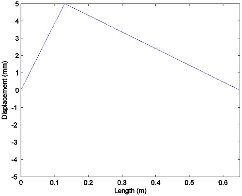
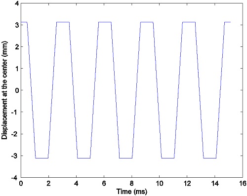
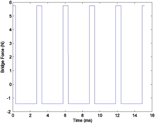
.The initial displacement for the case of plucking 5mm at the one fifth of the distance from the end is shown in Fig. 1, and the time evolution of the displacement at the center of the string and the force at the end are shown in Fig. 2 and Fig. 3, respectively with the length of the string of 650 mm, the spatial step  of 0.65 mm,
  , the velocity of 429 m /s, and the tension of 149 N .
III. Transmission Line Based Model
The voltage,  and the current,
  on a lossless transmission are given by
|
Fig. 1. Initial displacement of the string. |
|
Fig. 2. Displacement at the center. |
|
Fig. 3. Force at the end. |
 ,
,where  is the inductance, and
  is the capacitance per unit length of the transmission line.[10] From equation(6), wave equations for the voltage and the current are derived as
 .
.The phasor representations for the voltage,  and the current,
  are
are
 .
.The phasors,  and
and  on the transmission line are given by
 ,
,where  ,
,  ,
,  , and
, and  are the amplitude of the voltage and the current waves travelling to the
  , and to the
  direction, respectively, and
  is a complex propagation constant which is
  for the lossless transmission line, and
  is the characteristic impedance of the transmission line.
On the other hand, the reflection coefficient between an incident and a reflected wave at the end of the transmission line is given by
 ,
,where  is the load impedance. As represented in the equation(9), both voltage and current wave travel oppositely along the transmission line, and they are added to make a standing wave as in the string. The temporal solution of the wave equation given by equation(2) is consistent with the voltage and the current in phasor form given by equation(9). It was stated that only the current obeyed the wave equation, however so does the voltage as shown in the equation(7).[1-3] Moreover, the displacement of the string had an analogy to the current, and the momentum of unit length of the string to the voltage, and a rigid end to an open circuit. In the plucked string, two initial waves, which are given by plucking, and take same forms spatially, travel oppositely. From the equation(9), it is evident that the voltage has a direct correspondence to the displacement if
  and
and  take the same form spatially whereas the polarity of
  has to be reversed in order to replace the current with the displacement, which is not the case in the string. With the voltage replaced with the displacement, the rigid end corresponds to
  , which gives rise to
  , and a free end to
  , which produces
  . Since the polarity of the reflected wave at the rigid end is reversed to the incident wave, the rigid end is equivalent to the short circuit. The open circuit which has been replaced with the rigid end is equivalent to not the rigid but the free end. By making the polarity of
  to be reversed, and the both ends terminated with the open circuits, the current can be replaced with the displacement. However, the frequency response functions of the bodies of the string instruments generally carry a series of resonances characterized by the lower values of mechanical impedance, by which the frequency components in the vicinity of the those resonances sustain longer and are made to be dominant over others, and thus a specific timber of the instrument is accomplished. This reinforces the replacements of the displacement with the voltage and the rigid end with the short circuit.
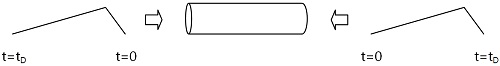
An initial voltage distribution along the transmission line corresponding to the initial displacement of the string can be obtained by having two voltage waves travelled from the both ends as shown in Fig. 4. Two voltage waves last as long as the time delay,  of the transmission line, and their shapes are spatially same, and are temporally symmetric to each other with respect to the half of their duration,
  . At
. At  , two voltage wave coincide each other, and are summed together to be doubled to make the initial voltage distribution.
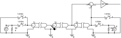
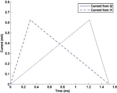
Based on the above mentioned ideas, the circuit for the string with the rigid ends is implemented with PSpice as shown in Fig. 5 consisting of the current sources, I1 and I2 having piecewise linear currents and three cascaded transmission lines, T1, T2, and T3. The time delays of the transmission line T1, T2, and T3 are set to 0.7575 ms, 0.7565 ms, and 0.001 ms, respectively summing up to 1.515 ms, which produces the same fundamental frequency as in the difference form for comparison, and its characteristic impedance to 8 Ω arbitrarily. The time delay of each of the cascaded transmission lines is set to monitor the voltage at the center of the transmission line and the voltage difference across T3 multiplied by 347,300 which correspond to the displacement and the force in the difference form, respectively, and thus the cascaded transmission lines can be replaced by a transmission line with the time delay of 1.515 ms and the same characteristic impedance of 8 Ω. The scale factor of 347,300 is obtained by 149 (tension)/ 0.00065 m (length of the string element in the difference form) 1.515/ 1000 (number of the string elements)/ 0.001. The initial voltage distribution is produced by the two piecewise linear currents as shown in Fig. 6. The current provided by current source I1 linearly increases from 0 mA at 0 ms to 0.625 mA at 0.303 ms which is one fifth of the total time delay of the transmission lines, and decreases back to 0 mA at 1.515 ms, while the current by I2 is symmetric to that by I1 with the respect to the half of the total time delay. The both current sources provide the voltage waves travelling to the opposite direction. At 1.515 ms, the voltage waves, which are obtained by the current flown into the transmission line multiplied by the input impedance of the transmission line from the end, coincide along the transmission line. At the same time, the switches, u3 and u4 open, and u1 and u2 close, by which the current sources and resistor, R2 and R4 are disconnected from the circuit, and the ends of transmission line, T1 and T3 are shorted, by which the voltage waves are ready to be reflected back and forth between the both ends.
In the transmission line, the input impedance is given by
 ,
,where  , and
, and  is the length of the transmission line. Since the term of
  is the multiples of
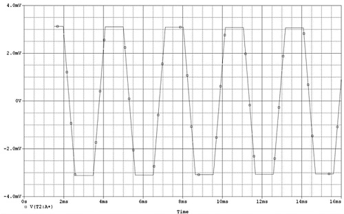
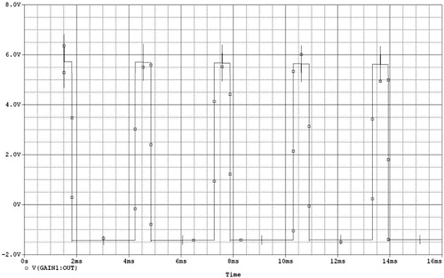
  for the fundamental frequency and its harmonics, the input impedance simply ends up with the load impedance of 8 Ω assuming that the ideal current source having the source impedance of infinity. The current from the current source I1 and I2 divided equally flows through the transmission line and resistor, R2 and R4, which produces the peak value of 2.5 mV. When two voltage waves coincide at 1.515 ms, the voltage level doubles to 5 mV which corresponds to the initial displacement of the string in the difference form given by plucking 5mm at the one fifth of the distance from the end. The voltage waveforms at the junction between the transmission line T1 and T2 and at the output of the gain in Fig. 5 are shown in Fig. 7 and Fig. 8, which are consistent with those from the difference form as presented in Fig. 2 and 3. The waveforms in Fig. 7 and Fig. 8 are recorded from 1.515 ms because it takes 1.515 ms to build the voltage distribution along the transmission line which corresponds to the initial displacement along the string given by plucking it.
In order to show the extensibility of the proposed string model to modeling of string and wind instruments, the short circuit to the right of T3 in Fig. 5 is replaced with a resistor of 2 Ω, and the voltage across the resistor, which corresponds to the displacement at the resistive load in the electrical equivalence, is presented in Fig. 9. In this case, the voltage reflection coefficient is given by
|
Fig. 7. Voltage at the center of the transmission line. |
|
Fig. 8. Voltage at the output of the gain. |
|
Fig. 9. Voltage across the resistor of 2 Ω. |
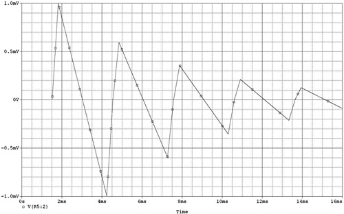
In Fig. 9, the voltage waveform between 1.515 ms and 3.03 ms is resulted from the sum of an incident voltage wave to the resistor of 2 Ω and its reflected wave, which produces the peak value of 2.5+2.5×(-0.6)=1 mV, the waveform between 3.03 ms and 4.545 ms from the sum of a reflected from the short circuit to the left of T1 and travelled wave to the resistor and its reflected wave with the peak value of -1 mV, the waveform between 4.545 ms and 6.06 ms from the sum of a reflected at the resistor between 1.515 ms and 3.03 ms, and reflected from the short circuit, and travelled back to the resistor, and its reflected wave with the peak value of 2.5×(-0.6) ×(-1)(1-0.6)=0.6 mV, the waveform between 6.06 ms and 7.575 ms from the sum of a reflected between 3.03 ms and 4.545 ms, and reflected from the short circuit, and travelled back to the resistor, and its reflected wave with the peak value of -0.6 mV, and so forth. From this experiment, it is expected that the proposed string model can be applied to modeling plucked string instruments such as guitar by connecting a circuit for a top plate coupled with air in a sound box in place of the resistor of2 Ω, and to struck and bowed string instruments by modifying the way the voltage wave is applied and connecting circuits for their bodies. It is well known that standing waves in an enclosed air column are analogous to those on the string, and thus the proposed model is also expected to be applicable to even wind instruments.[11]
IV. Conclusions
In existing transmission line based string models, the displacement of a string had an analogy to the current on a transmission line, and a rigid end to an open circuit. In this paper, it is shown with the theory of the transmission line that the displacement corresponds to the voltage on the transmission line, and the rigid end to a short circuit. By applying these correspondences and the presented method of the excitation of the transmission line, a novel transmission line based plucked string model is proposed. The proposed model is validated with circuit simulations by demonstrating that the displacement of the string and the force at the end from the difference form are consistent with those from the proposed model. Moreover, the applicability of the proposed string model to modeling string and wind instruments is presented. Researches on modeling string and wind instruments using the proposed string model will succeed.
