

I. Introduction
II. Mechanisms of acoustic generation
III. Acoustic design methods
IV. Launch pad design for epsilon solid launcher
4.1 Methods
4.2 Strategies for acoustic-load mitigation
4.3 Post-Flight Analysis
V. Summary
I. Introduction
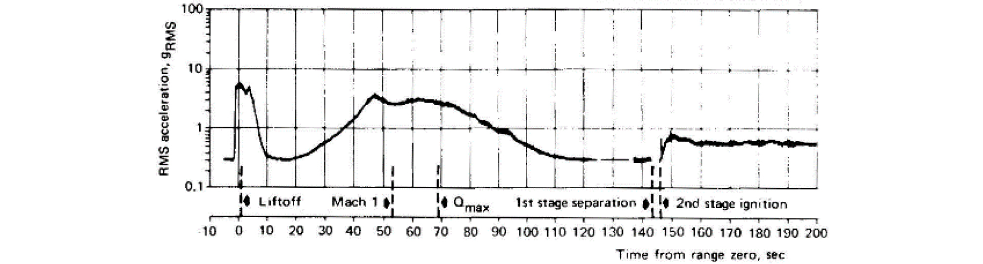
Launch vehicles are exposed to severe vibration and shock during flight. Fig. 1 shows an example of vibration measured with an accelerometer mounted on the upper stage of a launch vehicle. There are two major peaks, which appeared at 0 s ~ 5 s and 45 s ~ 80 s. The former is caused by acoustic waves generated from exhaust jets of the propulsion systems. The latter is due to aerodynamic vibration that occurs under transonic or maximum dynamic pressure flight regimes. The aerodynamic vibration is generated by oscillating shock waves, a turbulent boundary layer, and separated flow behind protuberances. This study focuses on the acoustic loads that appear at liftoff.
The retired M-V solid launcher generated 3,700 kN of thrust at liftoff, and overall acoustic power radiated from the exhaust jet was estimated to be 197 dB. The Overall Sound Pressure Level (OASPL) measured by a microphone located outside the payload fairing reached 157.6 dB, and OASPL measured inside the payload fairing was 144 dB.[2] Since electronic and mechanical components in the satellite and the launch vehicle are exposed to an acoustic environment exceeding 140 dB, predicting and reducing liftoff acoustics is one of the important design considerations in developing launch vehicles.
Prediction and reduction of liftoff acoustics require knowledge in two domains, aeroacoustics and vibroacoustics. Aeroacoustics deals with the generation of acoustic waves from exhaust jets, their interaction with the launch pad, and the propagation to the payload fairing. On the other hand, vibroacoustics is concerned with the transmission of acoustic waves through the fairing structure and the effects on the satellite inside. This article focuses on aeroacoustics and introduces the latest studies on the mechanism of acoustic generation and design methodologies of the launch pad. Then, the example of launch pad design for the Epsilon solid launcher, developed by the Japan Aerospace Exploration Agency (JAXA), is introduced with post-flight analysis.
II. Mechanisms of acoustic generation
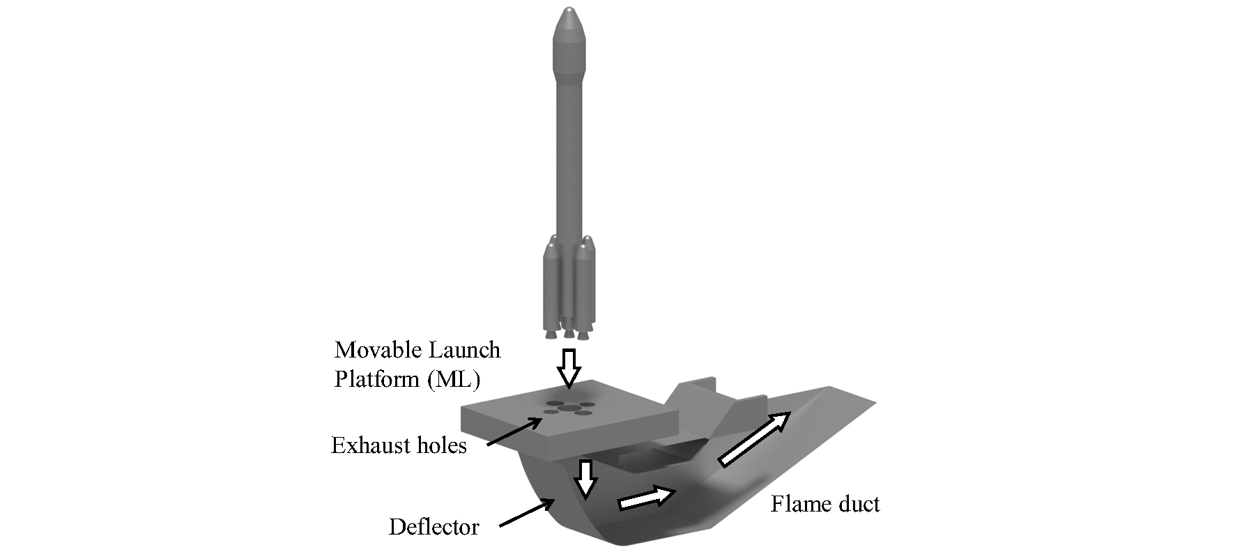
Fig. 2 is a schematic of a typical launch pad. The launch vehicle is mounted on a Movable Launch pad (ML) and transported from a vehicle assembly building to the final launch pad location. The ML has exhaust holes to direct the exhaust jets into a flame duct. The flame duct is usually constructed underground. A deflector in the flame duct safely deflects the hot exhaust downstream.
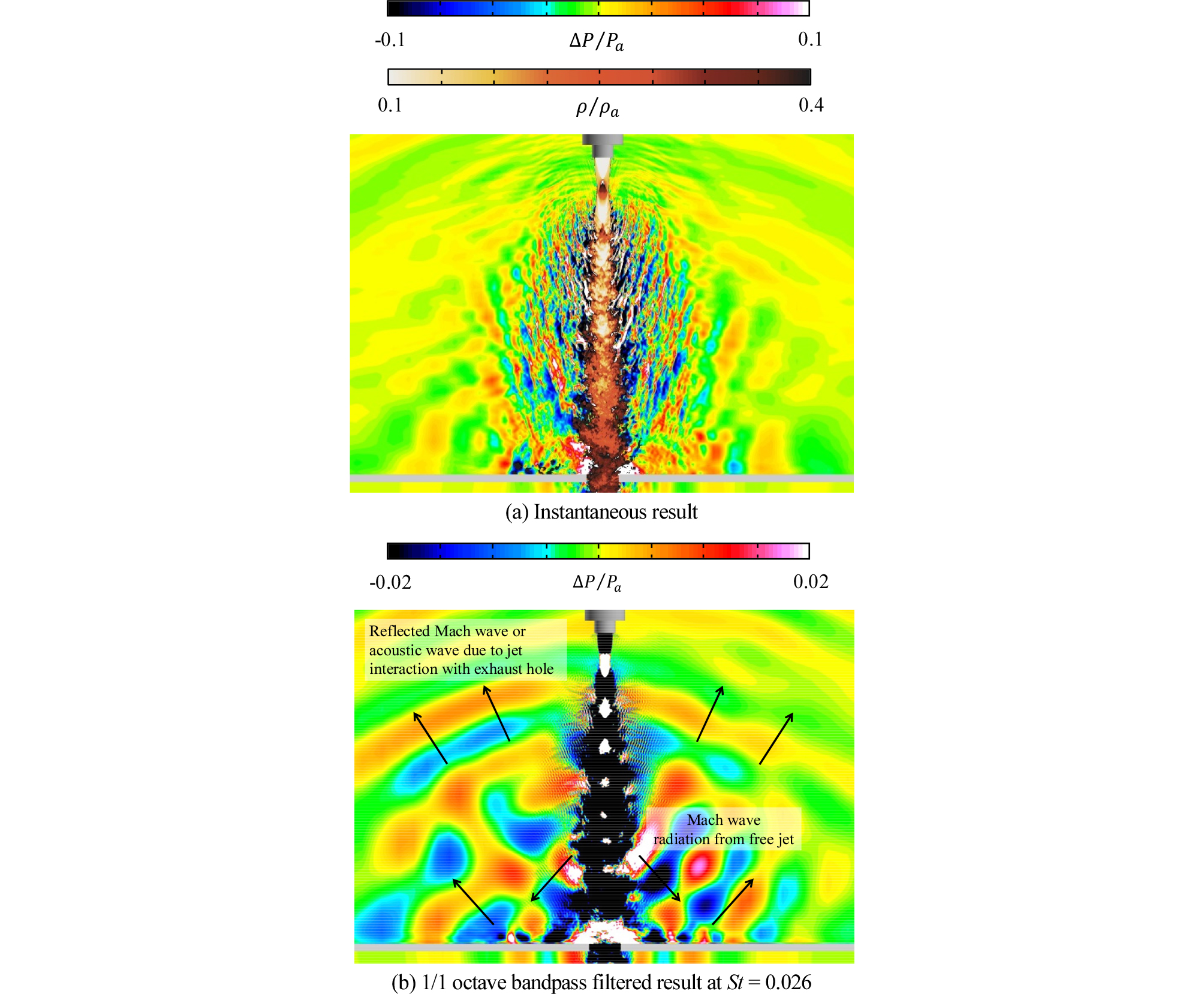
The exit Mach number of the exhaust jet from a rocket engine is at least 3, and the exit static temperature can be over 1000 K. The Mach wave is radiated from the free jet region of the exhaust jet due to its large-scale turbulent structure.[3] Empirical models proposed by Eldred et al. and Varnier are representative of the acoustic prediction method.[4,5] According to the Varnier’s model, the major source of the Mach wave is generally around 10D downstream from the nozzle exit. Note that D is the nozzle exit diameter. The major acoustic-emission direction of the Mach wave is roughly 50 deg from the direction of jet flow. As shown in Fig. 2, when the launch vehicle rises to 10D above the launch pad, the region of the jet that radiates the Mach waves appears from the exhaust hole of the ML then begins to contribute to the acoustic load on the launch vehicle. The maximum acoustic level is usually observed when the launch vehicle is elevated to approximately 20D. To investigate the acoustic field appearing above the ML, numerical analysis using Computational Fluid Dynamics (CFD) was conducted to understand the hydrodynamic and acoustic field generated by impingement of a supersonic jet exhausted from a 1/42-scale solid motor on an infinite flat plate with an exhaust hole.[6] Instantaneous CFD result of the hydrodynamic field visualized by density normalized by ambient density , and acoustic field by pressure fluctuation normalized by ambient pressure are shown in Fig. 3(a). In this result, the diameter of the exhaust hole and height of the nozzle exit from the ground were 2D and 20D, respectively. The Mach waves are radiated from the large-scale turbulent structure in the free jet shear layer and propagate obliquely downstream. 1/1 octave band filter is applied to the time series data, and results at a center frequency of 4000 Hz (Strouhal number St = 0.026) is shown in Fig. 3(b). The acoustic waves returning to the launch vehicle are clear. The acoustic waves originated in the Mach waves reflect off the flat plate. The free jet grows up as it proceeds downstream and interacts with the edge of the exhaust hole. This interaction is another source of acoustics propagating to the vehicle.[7] It is not clear how much each contributes to the acoustic environment of the launch vehicle.
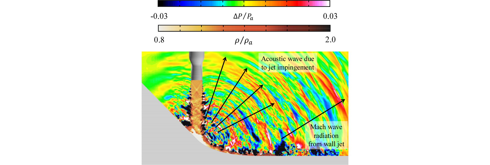
Immediately after liftoff, the high-speed exhaust jet enters the flame duct through the exhaust hole then impinges on the deflector. This causes the different acoustic waves from the Mach wave radiation from the free jet. CFD is applied to analyze the hydrodynamic and acoustic field generated when a supersonic cold jet with the Mach number of 1.8 impinges on the deflector.[8] Fig. 4 shows the result. Same with Fig. 3, the hydrodynamic and acoustic field is visualized by , and , respectively. The deflector studied here was initially inclined at 45 deg then smoothly connected to the ground. The distance from the nozzle exit to the deflector was set to 5D. Two types of the acoustic waves can be seen in Fig. 4. One propagates in all directions from the impingement point, while the other is generated from the wall jet and propagates obliquely downstream. From the directivity angle, the latter is probably the Mach wave generated by the large-scale vortex structure of the shear layer, similar to that of the free jet. While the former is thought to be generated by the interaction between the vortex structure of the jet shear layer and a plate shock wave appeared at the jet impingement region, the interaction of the vortex structure with tail shock waves generated inside the wall jet also contributes to the former acoustic wave.[9,10,11,12]. However, the cause of the waves due to jet impingement has not been clarified, and further research is necessary. At the launch pad shown in Fig. 2, the acoustic waves generated due to the jet impingement propagate in all directions then are shielded by the ML located above the deflector. Therefore, the acoustic waves due to the jet impingement do not propagate directly to the launch vehicle. Together with the Mach waves radiated from the wall jet, the acoustic waves due to the jet impingement propagate to the launch vehicle through the exit of the flame duct.
As seen above, the acoustic generation mechanism changes with the elevation of the launch vehicle. Panda et al. obtained a similar conclusion from visualizing the acoustic sources of an actual flight by the beam-forming technique.[13] In designing the launch pad, it is necessary to consider the effect of acoustic sources that change with the elevation of the launch vehicle.
III. Acoustic design methods
In the development of launch vehicles, design requirement for the Sound Pressure Level (SPL) inside the payload fairing is determined. Then the SPL outside the payload fairing is determined, considering the transmission loss due to the payload fairing. The launch pad is designed to satisfy the SPL outside the payload fairing.
The acoustic design procedure for the launch pad is shown in Fig. 5. The launch pad design is divided into preliminary and detailed designs. Conventionally, the preliminary stage of design uses the empirical method, a simplified model test, and past flight data if available. The detailed design mainly involves a subscale model test.

The empirical method described in NASA SP-8072[4] is used in the preliminary design. This method was based on results obtained from static-firing tests and flights. It can predict the SPL at the observation point easily, but this method is applicable mainly to the Mach wave radiation from the free jet. The other source of acoustics described in Section II were modeled by changing the acoustic efficiency; their generation mechanisms were not considered. (The acoustic efficiency is defined as the ratio of the sound power to the mechanical power of the exhaust jet.) Many studies have been made to improve the prediction accuracy in the framework of the empirical method.[5,14,15,16]
In preliminary design, a simplified model test can also be used instead of the empirical method. The MARTEL test stand of the Centre National d'Etudes Spatiales (CNES) is a representative type. Acoustic testing using overexpanded hot jets having an exit Mach number of about 3 can be done in a semi-anechoic test stand. Gaseous hydrogen and air are employed. Detailed specification of the jets is given in the references.[17,18] Although an acoustic environment similar to the full-scale launcher is not possible using the MARTEL test stand, acoustic testing can easily be done repeatedly. Parametric studies for the launch pad configuration including water injection system for Ariane 5, VEGA, and Ariane 6 have been done so far.[17,19,20]
The launch pad used in the past has been modified and reused without need for developing a new one in some cases. In such case, the preliminary design (very occasionally, the detailed design, too) is performed based on past flight data.
Subscale model testing is generally done in detailed design. In the development of launch vehicles such as the Space Shuttle, Ares I, Space Launch System (SLS), Ariane 5, and VEGA, subscale model test having 1/15 to 1/20 scale have been performed.[7,19,21,22,23,24]
The development of the Space Shuttle used a 6.4 %-scale model test. Assuming that the same nozzle exit velocity is obtained between the subscale and full-scale engines, the acoustic power W and frequency f are expressed as follows using scale factor S.
| $$W_{full}=S^{-2}W_{sub}.$$ | (1) |
| $$f_{full}=Sf_{sub}.$$ | (2) |
The subscripts full and sub represent the full scale and subscale, respectively. Using above equations, the flight data of the Space Shuttle was compared with the subscale test results. An accuracy of roughly 5 dB in 1/3 octave band Sound Pressure Level (SPL) was achieved.[21] In the development of the Ares I, a 1/20-scale model test was conducted. Very good prediction accuracy of approximately 2 dB in OASPL was achieved.[22]
In addition to predicting the full-scale acoustic level, the acoustic loads also needed to be reduced to satisfy design requirement. In the development of the Ariane 5 and VEGA, experiment was conducted at MARTEL test stand to determine whether the flame duct should be covered or uncovered to reduce the acoustic level.[17,20] In many launch pads, a large amount of water, several times the total flow rate of the engine exhaust jets, is injected for acoustic attenuation.[25] Many studies have been conducted, using simplified model tests and subscale model tests, to design a water injection system.[7,17,20,22,26,27,28] The mechanism of acoustic attenuation by water injection has not been clarified. In the subscale model test, the effect of the scale size on the attenuation level should be carefully examined.[29]
With the improvement of CFD technology and the computing performance increase of High Performance Computers (HPCs), improved CFD-based design has become available. As mentioned above, the empirical model proposed by NASA SP-8072 is based on the Mach wave radiation from the free jet, and the limitation in the range of application is clear. As shown on the right side of Fig. 5, CFD can be used both in the preliminary and detailed designs. The CFD methods used for the preliminary and detailed designs must be different. They are named as CFD1 and CFD2, respectively, here. Table 1 shows an example of CFD methods used in the development of the Epsilon.[30,31] Parametric study for the launch pad configuration is done in the preliminary design, so the need for CFD1 is throughput rather than fidelity. Therefore, implicit Large-Eddy Simulation (LES) considering only the numerical viscosity originating in grid resolution was employed. Second-order accuracy was achieved for the convective and viscous terms and for time integration. The cut-off frequency of CFD1 was set to 150 Hz, which is not enough to analyze the acoustic environment of the launch vehicle. However, using 3072 cores of the former JAXA’s HPC, JSS (Fujitsu FX1, 31 TFlops) operated from 2009 to 2014, results could be obtained within 3 days per case. CFD2 used in the detailed design requires fidelity rather than throughput. The zonal hybrid LES / Reynolds-averaged Navier-Stokes (RANS) method was employed. The turbulent boundary layer on the deflector was computed by RANS, and off-wall region were computed by LES. Convective terms were evaluated by a high-resolution method with 6th order accuracy, and the cut-off frequency reached 800 Hz using 2048 cores of the JSS (20 TFlops) for 2 to 5 months. Validation of CFD2 was performed using the results of the subscale model test. Prediction accuracy of approximately 4 dB in OASPL was confirmed.[30,32] Note that JAXA’s HPC is expected to be renewed this fiscal year, and will achieve higher computing performance by 144 times than the former JSS. CFD analyses will be performed in a shorter time. CFD has also been used in the development of the H3 launch vehicle under development in Japan, and in the development of VEGA.[6,33,34]
Table 1.
CFD methods used in development of Epsilon solid launcher.
IV. Launch pad design for epsilon solid launcher
Design requirements imposed at the beginning of the Epsilon development were that: (1) the acoustic level inside and outside the payload fairing would be 140 dB and 147 dB in OASPL, respectively, and (2) the existing launch pad for the M-V in Uchinoura Space Center (USC) would be utilized as much as possible. Since the thrust at liftoff was 3,700 kN for the M-V and 2,000 kN for the Epsilon, the acoustic power generated at the exhaust jet was estimated to be 3 dB lower for the Epsilon. The OASPL at the outside of the payload fairing was 157.6 dB for the M-V. Even considering the difference in the engine, a reduction of 8 dB was required for the launch pad design.
4.1 Methods
At the beginning, the empirical method described in NASA SP-8072 was employed. The required acoustic level could not be satisfied unless the cliff of the launch site was dug into the scale of tens of meters to create the flame duct. This result violated the other design requirement to reuse the existing launch pad for the M-V as much as possible. The application range of the empirical method was known to be limited, so CFD methods listed in Table 1 were used heavily in both the preliminary and detailed designs. The detailed design also used subscale model testing. Considering the similarity of acoustic spectra, a 1/42-scale solid motor was employed in that test. The nozzle exit velocity was designed to be the same as the full-scale motor, and the Reynolds number based on the nozzle exit conditions was 2.2 × 10⁵. The propellant of the 1/42-scale motor had almost the same properties as the full-scale motor, so that the acoustic power Wfull and frequency ffull were estimated by Eqs. (1) and (2). The schematic of a test stand is shown in Fig. 6. The 1/42-scale solid motor was hung from the top of the test stand via a load cell for measuring thrust and a hydraulic cylinder for changing the elevation. The subscale launch pad was located below the solid motor. Three microphones were mounted around the payload fairing. Additional microphones were located 60D from the jet impingement point to obtain validation data for CFD and to investigate acoustic feature of the launch pad. Sufficient repeatability was confirmed in advance. The measurement error of the microphones was estimated to be 2 dB. Details of the subscale test can be found in the reference.[30]
4.2 Strategies for acoustic-load mitigation
As described in Section II, the dominant acoustic waves just after liftoff are generated by the jet impingement on the deflector and the Mach wave radiation from the wall jet. As the launch vehicle is elevated, the dominant sources of acoustics change to the reflection of the Mach wave from the free jet and the interaction between the free jet and the ML. The acoustic sources that change according to the vehicle’s elevation should be taken into account in the design of launch pads. The baseline configurations for the preliminary and detailed designs are shown in Fig. 7. Fig. 7(a) is based on the launch pad for the Minotaur 1 at the Wallops Flight Facility of NASA. On this type of launch pad, the launch vehicle is mounted at a certain height above the ground. As described in Section 4.2.1, the effect of the Mach wave radiation from the free jet can be reduced by raising the launch mount. Based on the CFD results and structural design, the shape of the launch pad in the detailed design was determined by considering the installation on the existing launch pad. Finally, the configuration shown in Fig 7(b) was obtained as the baseline for detailed design. Due to space limitations, not all the results of the preliminary and detailed designs are shown here, but three strategies for acoustic attenuation are explained below.
4.2.1 Position and shape of launch mount
As mentioned in Section II, when the vehicle is elevated, the Mach wave radiated from the free jet is reflected from the ground or launch complex, and then returns back to the launch vehicle, which imposes an acoustic load. To increase the propagation distance of the Mach wave and reduce its effect on the launch vehicle, the launch mount was determined to be located as high as possible from the ground. The Epsilon was planned to be assembled in the existing vehicle assembly building. The height of the launch mount was constrained by the height of the building.
Additional consideration for designing the launch mount was to minimize the interaction of the jet with the launch mount, because the interaction generates the acoustic waves. In the Epsilon, the projected area of the launch mount was minimized, and the launch mount was tapered to reduce the interaction.
4.2.2 Deflector shape
Just after liftoff, the dominant acoustic waves are generated by the impingement of the exhaust jet on the deflector, as discussed in Section II. The acoustic waves due to this are related to the strength of the plate shock wave. As the mounting angle of the deflector to the ground increases, the strength of the plate shock wave weakens, so the acoustic waves due to jet impingement can be reduced.[35,36] The tail shock waves are also a source of acoustics. By increasing the curvature of the deflector and gradually changing the flow direction, the tail shock waves are weakened, and eventually the acoustic level can be reduced.[8,35] In the preliminary design, the effect on the acoustic level was evaluated by CFD for three explanatory variables: (1) the height of the launch mount, (2) the initial inclination angle of the deflector, and (3) the curvature of the deflector. About twenty deflector shapes were evaluated.
4.2.3 Flame duct
The vertical flame duct of the baseline shapes shown in Fig. 7 had four side walls, but the side wall facing the deflector outlet was fully open. Fig. 8 shows the CFD result for Fig. 7(b). The Mach waves radiated from the jet flowing into the vertical flame duct propagate outward from open side, reflect off the ground, and head back to the launch vehicle. Based on this, a front cover was installed on the open side to shield against the Mach waves. As a result, reduction of OASPL by 3 dB at the payload fairing was obtained in the subscale model test when the elevation of the launch vehicle was 14D. On the other hand, further reduction was required at low elevations to satisfy the design requirement. Therefore, a ground flame duct was designed to shield the acoustic waves due to the jet impinging on the deflector and the Mach waves radiated from the wall jet. As a result, reduction by 3 dB in OASPL at the payload fairing was also obtained in the subscale model test, when the elevation of the launch vehicle was 8D.
The launch pad for the Epsilon built at USC is shown in Fig. 9. The launch mount and the vertical flame duct were attached to a boom that carries the launch vehicle from the vehicle assembly building to the launch pad. The ground flame duct was constructed on the ground. A triangular roof was attached to the ground flame duct to reduce the reflection of the Mach waves radiated from the free jet. The deflector inside the ground flame duct was designed based on the CFD results obtained in the preliminary design. The launch pad of the Epsilon does not have a large underground flame duct or water injection system, resulting in a compact launch pad compared to others in the world.
4.3 Post-Flight Analysis
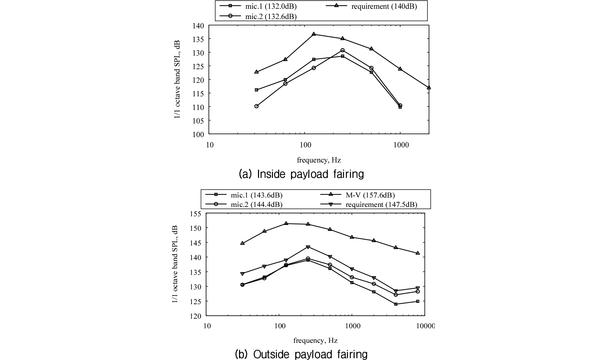
In the Epsilon’s first flight, microphones were installed both inside and outside the payload fairing to validate the launch pad design. Results of two microphones attached inside the payload fairing are shown in Fig. 10(a). Although there are differences in the two measurements due to the different locations, those results satisfied the design requirements at all frequencies. The launch pad designed for the Epsilon was compact without an underground flame duct or water injection system, but the flight results demonstrated a quieter acoustic environment than other small- and medium-sized launch vehicles. Fig. 10(b) compares the measurements by the microphones attached at different locations outside the payload fairing with the design requirements and the measurement of the M-V. The results of the Epsilon satisfied the design requirement in all frequencies. In addition, the results were significantly lower than that of the M-V. OASPL measured outside the payload fairing of the Epsilon was at most 144.4 dB, which means that the acoustic environment was reduced by about 13 dB compared with the M-V. Although the difference of the acoustic level due to the motor size was 3 dB as mentioned earlier, the acoustic level could be reduced by 10 dB through the improvement of the launch pad. The flight data usually have large variations, but the results of four Epsilon’s flights so far did not show remarkable variations. Therefore, the effectiveness of the launch pad designed using CFD was confirmed.
V. Summary
This article has presented the latest information of the mechanism of acoustic waves generated by launch vehicles at liftoff, as well as introducing acoustic design methods for the launch pad. Then, as an example, development of the launch pad for the Japanese Epsilon solid launcher is outlined. The launch pad for the Epsilon was designed by using CFD together with subscale model testing. Through the post-flight analysis, it was found that reduction of the acoustic level by 10 dB compared to the previous M-V launcher was achieved, in addition to satisfying the design requirement.
The launch vehicle is an expensive transportation system that cannot fail. Cost and reliability are often the main development goals. Reducing the acoustic loads on the satellite leads to the reduction of satellite development cost. Therefore, reducing the acoustic loads at liftoff is also an important design issue that increases the value of the launch vehicle.
It is also a fact that mechanisms of acoustic waves generated at liftoff of a launch vehicle are not sufficiently understood yet. Study of acoustic generation is still an interesting topic to academic researchers. In addition, there is a possibility for engineers to achieve further reduction of the acoustic loads by modifying the shape of the launch pad. I hope this article will help to promote cooperation between Korea and Japan in the research and development of liftoff acoustics.
