

I. Introduction
II. QPSK system and waveform shaping filter
III. Configuration of the simulations
IV. Results and Discussion
V. Conclusions
I. Introduction
The underwater acoustic communication channel is known to exhibit a frequency selective channel by multi-path delay spread in a multipath channel such as the shallow water. The ISI (Inter-Symbol Interference) occurs due to multiple reflections from the water surface and the seabed affected by the reflected waves, resulting in degradation of underwater acoustic communication performance in the shallow water.[1-3] As the channel’s bandwidth becomes narrow due to the influence of the ISI, it shows the frequency selective channel.[4-6] For the proper underwater acoustic communication in these situations, we concentrated on the waveform shaping filters which is known helpful to prevent ISI.[7,8] So, we investigate the effect of waveform shaping filter on the output signal of the transmitter on the underwater acoustic communication. The applied communication system is the QPSK (Quadrature Phase Shift Keying) system[9] which has four different states in each symbol transmission. For the investigation of the effects of waveform shaping filters, the raised cosine filters are applied with three different roll-off factors.[8,10] And we suggest and evaluate a modified raised cosine filter on the same communication condition. The performance of the modified raised cosine filter was found that the attenuation of the side-lobe level was more than -10 dB compared with other raised cosine filters at same time length and same frequency bandwidth.
II. QPSK system and waveform shaping filter
The QPSK modulation and demodulation system is one of the digital communication systems. There are two channels - I channel and Q channel - in the QPSK system as shown Fig. 1(a) and (b). The transmitted signal is demodulated separately to two output signals using cosine signal or sine signal with same carrier frequency of modulation system. And then output signals are converted to 4 states sequences [00 01 10 11] through the decision processor for each channel with the phase variation shown as Fig. 1(c).
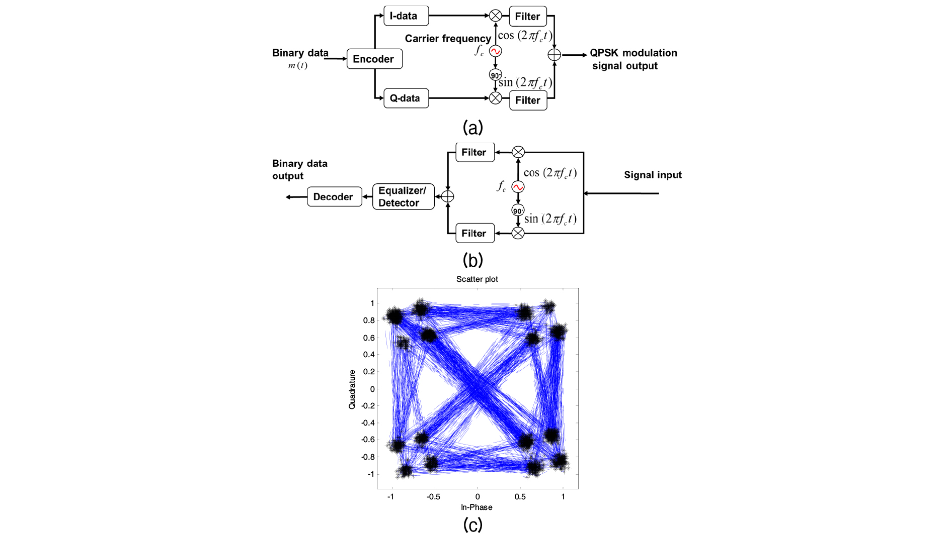
In Fig. 1(a) and (b), there are some filters on the behind of the carrier signal multiplying in the modulation and on behind of the carrier recovery in the demodulation, it is called the matched filter which has three reasons to be used. If the phase varies a 180°, the phase inverted time signal will ask very rapid response on the transducer. But it is very hard jobs on common analogue device, so that it is the first reason why we use some filter. The second reason is that the bandwidth of the signal might be limited on digital multi-carrier modulation method like as OFDM (Orthogonal Frequency-Division Multiplexing). The last reason is to detect and decide high probability without ISI on demodulated signal. For these reasons, it is commonly used the raised cosine filter as follows,[7,8]
| $$h_{rcos}(t)=\sin c\left(\frac tT\right)\frac{\cos\left(\beta\pi t/T\right)}{1-\left(2\beta t/T\right)^2},$$ | (1) |
where sinc, 𝛽, T mean the sinc function, the roll-off factor, and the reciprocal of the symbol-rate. It comes from the sinc function and cosine function. If the roll-off factor 𝛽 is zero, the impulse response would be just sinc function with very strict band limit in the frequency domain.
The time signal and frequency responses represented according to the roll-off factor in Fig. 2. In Eq. (2), as the range of t is set from -3 to 3 with 1/T intervals, all the length of the waveform shaping filter are chosen by 6×T. Each number of (∙) means the roll-off factor. Those of solid line, dash-single dotted line, and dashed line are chosen by 0.0, 0.5, and 1.0, respectively. The symbol ○ means the cutoff frequency given by -6 dB point in Fig. 2(b). Each first side-lobe level are represented by about -23 dB, -45 dB, and -57 dB according to the roll-off factor, respectively. It can be seen that as the roll-off fact increases, the attenuation of the first side lobe decreases, and the transition bandwidth becomes wider.
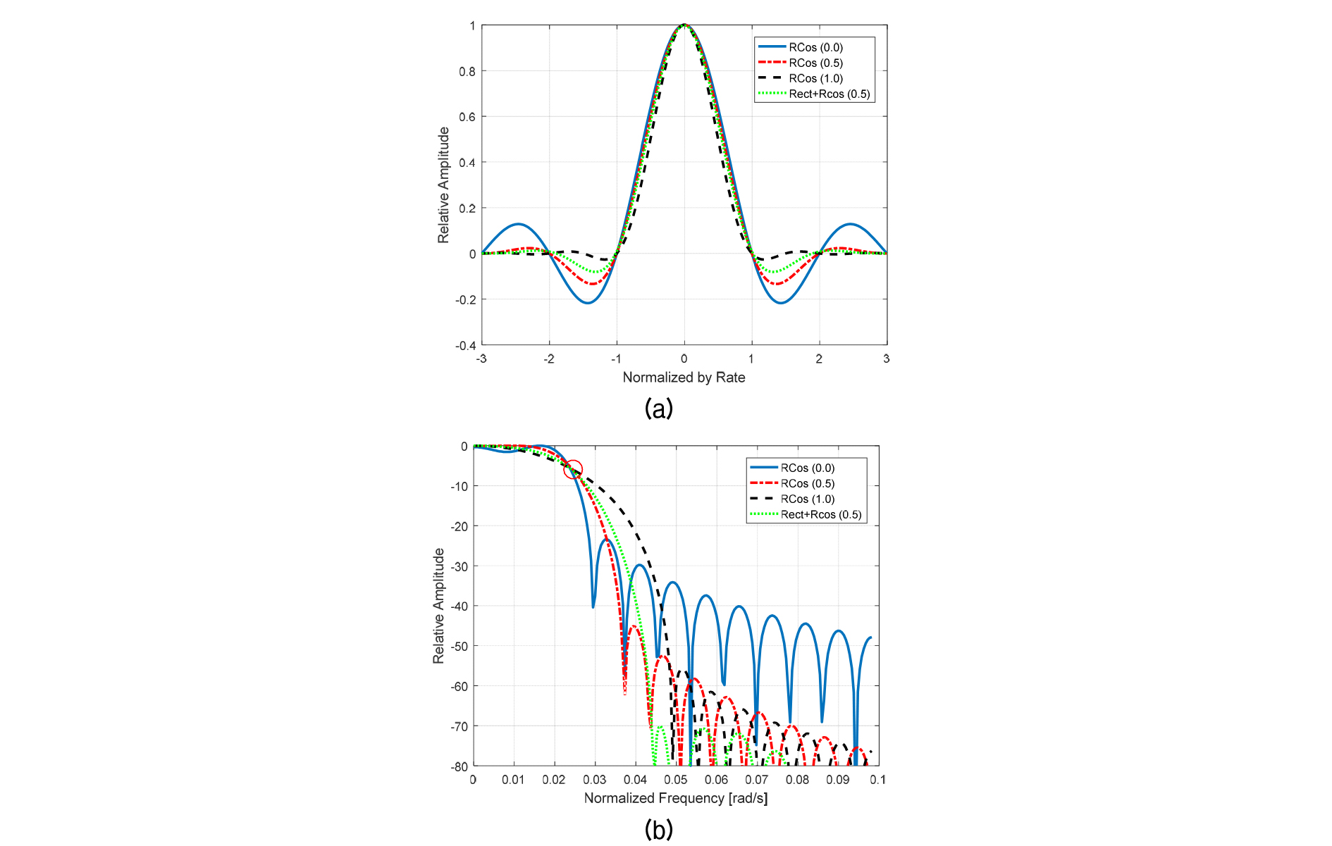
As the ideal filter. Since the ideal filter characteristic is the large attenuation of the side lobe and narrow transition bandwidth, a new filter is modified by combining a raised cosine filter and a rectangular window with the narrowest transition bandwidth among the window functions.
In Fig. 2, the dotted green line is a new modified raised cosine filter combined by a raised cosine filter (the length is to be 5×T owing to the range of t is set from -3 to 3 with 5T/6 intervals) and the rectangular window (the length is T), so that the length of filter is given by 6×T. The first side-lobe level is given by about -70 dB.
where * and rect means the convolution operator and rectangular window, respectively.
III. Configuration of the simulations
Fig. 3 shows the configuration of sea experiment and its sound velocity profile in shallow water located in the George Island near to Busan city in Korea. The range between a transmitter and a receiver is set to be 100 m, or 400 m. Each depth of the receiver and the transmitter are set to be 7 m and 10 m, respectively. The channel characteristics of the numerical simulation are obtained as Fig. 4 from this environment parameter as shown Fig. 3. We assumed that the channel impulse responses had only 5 signals as shown in Eq. (3) - direct, bottom reflected, surface reflected, bottom-surface reflected, and surface - bottom reflected signals.

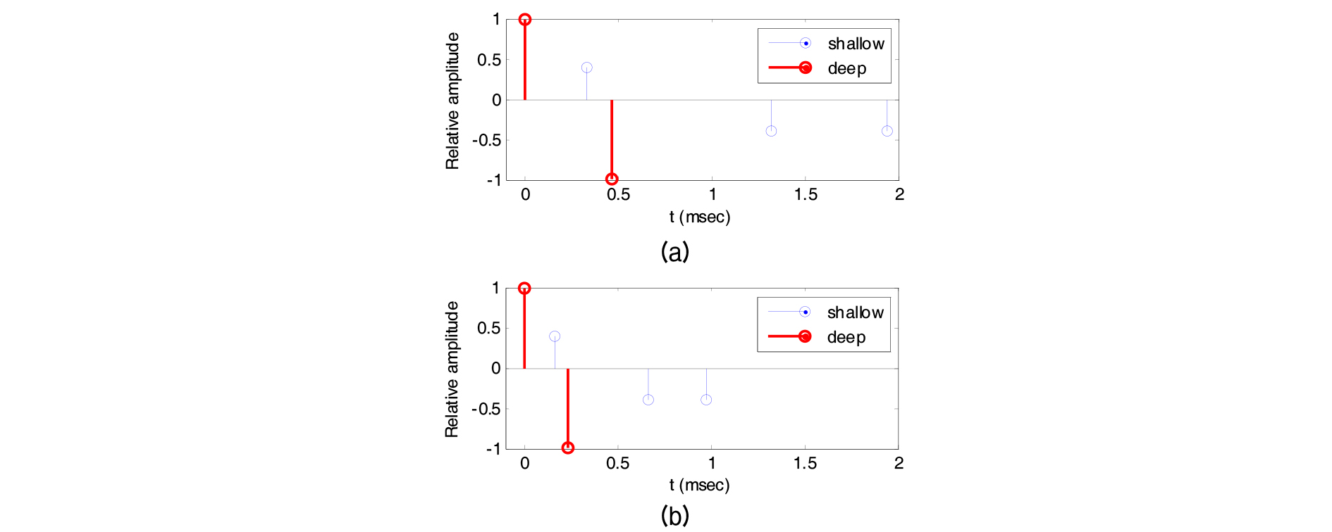
| $$h(t)=\sum_{n=0}^Na_n\delta\left(t-\tau_n\right),$$ | (3) |
where Here, an is the nth multi-path signal’s amplitude, 𝜏nis the nth multi-path delay time, and N is chosen by 4. The specific experimental parameters are given in Table 1. The transmitted image is the standard Lenna image consisting of 9,800 bits of data.
Table 1. Simulation and experimental parameters.
IV. Results and Discussion
For the check of the channel’s characteristic, the channel’s coherence bandwidths are calculated from Eqs. (4) - (6). The average delays and are respectively given by [6,9]
| $$\overline{\tau^2}=\frac{{\displaystyle\sum_n}a_n^2\tau_n^2}{{\displaystyle\sum_n}a_n^2},\;\overline\tau=\frac{{\displaystyle\sum_n}a_n^2\tau_n}{{\displaystyle\sum_n}a_n^2},$$ | (4) |
where anis the amplitude of the nth path delay .
From Eq. (4), the effective delay spread is given by
| $$\tau_{rms}=\sqrt{\overline{\tau^2}-\left(\overline\tau\right)^2}.$$ | (5) |
The relationship between the effective delay spread and the channel’s coherence bandwidth is given by
| $$BW_{coh}\simeq\frac1{5\tau_{rms}}.$$ | (6) |
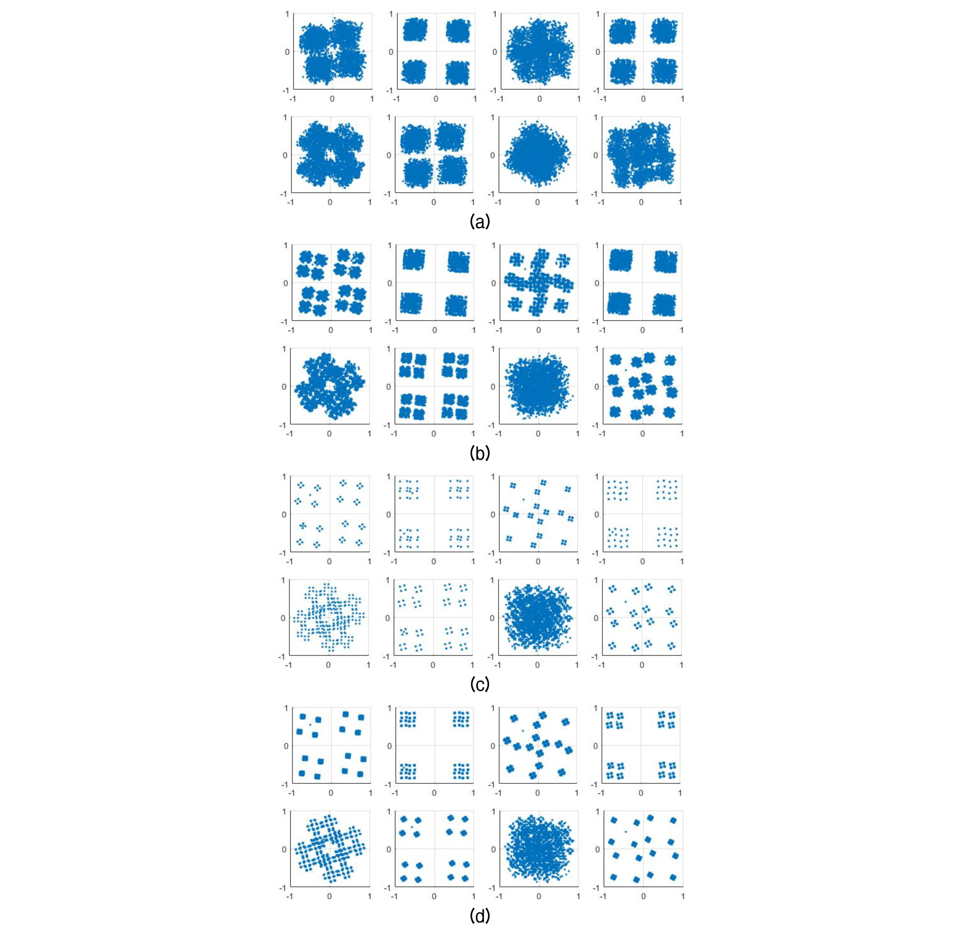
The channel’s coherence bandwidth were calculated about 200 Hz and 760 Hz at 100 m and 400 m in shallow water, respectively. It means that 400 symbol rates per second (sps) on 100 m is only belonged to frequency-selective fading channels, so that the adaptive equalizer are required. Except this, all communication channels would be belonged to non-frequency-selective fading channels, and then only the phase compensation is required. Fig. 5 shows the constellations with carrier frequency 16 kHz in shallow sea - (a) Rcos (0.0), (b) Rcos (0.5), (c) Rcos (1.0), and (d) Rect+Rcos (0.5). From left top to right bottom, distance / sps orders were 100 m / 100 sps, 400 m / 100 sps, 100 m / 200 sps, 400 m / 200 sps, 100 m / 400 sps, 400 m / 400 sps, 100 m / 800 sps, and 400 m / 800 sps. It can be seen that as the roll factor increases, the constellation separates more clearly, and that the proposed filter is more concentrated. Table 2 shows the symbol per rate according to Fig. 5. Comparing the each result, the error rates were decreased in all cases. Also, it can be seen that the error decreases as the roll factor increases, and the proposed method shows the best results in all cases. This is attributed to the high attenuation and narrow transition bandwidth of the proposed filter.
Table 2. Simulation results.
V. Conclusions
In this paper, we investigated the effect of raised cosine waveform shaping filter on the underwater acoustic communication. The applied communication system was the QPSK system. For the investigation of the effects of waveform shaping filters, the raised cosine filters were applied with different roll-off factor, which are 0.0, 0.5, and 1.0, respectively. And modified raised cosine filter was proposed with combining rectangular window and raised cosine filter.
Comparing the each result, it can be seen that the error decreases as the roll factor increases, and the proposed method shows the best results in all cases. The bit error rate was reduced from the minimum 1.0 % to the maximum 32 % compared with other raised cosine filters. This result is expected to be useful in an environment where the bandwidth due to reflections is narrowed, such as in the shallow water.
