

I. Introduction
II. Theoretical background in time reversal processing
2.1 Conventional passive time reversal processing
2.2 Adaptive passive time reversal processing
III. BLAC18
IV. Results of the at-sea experiment analysis
4.1 Channel impulse response
4.2 Results of analysis based on passive TRP
V. Conclusions
I. Introduction
Low-frequency signals are mainly used in long-range underwater communication systems spanning over 10 km owing to the increase in transmission loss with an increase in the communication range.[1,2,3,4,5,6,7,8,9,10,11,12,13,14,15,16,17,18,19,20] Because a decrease in the frequency band translates into a decrease in the data rate, the data rate reduces with increasing communication range.[21]
To achieve an effective increase in data rates under such conditions, research on Multiple-Input Multiple-Output (MIMO) communication based on Time Reversal Processing (TRP) has been conducted.[22],23,24,25,26,27,28] In the MIMO environment, because two or more sources transmit signals simultaneously, the data rate can be increased in proportion to the number of sources compared with the data rate when the number of sources is one. Song reported the results of applying the TRP technique, which is considered to be an optimal solution for canceling Inter- Symbol Interference (ISI) caused by multipath, to MIMO communication signals in a shallow water environment.[22] However, one limitation of conventional TRP is that it cannot cancel the interference between sources occurring in a multi-source environment. For interference cancellation, studies have been performed on techniques such as the Minimum Variance Distortionless Response (MVDR)[23,24,25] and successive interference cancellation.[24,25,26,27,28] These studies were conducted in shallow sea environments, and Shimura reported the results of applying MVDR-based adaptive TRP techniques to long-range deep-water environments.[15] The analysis results of MIMO experimental data of hundreds of kilometers, in waters over 4,000 m in depth, near 20° north latitude and 140° east longitude were presented, and Binary Phase Shift Keying (BPSK) modulated signals, the most basic modulation scheme, were transmitted. This was the only case in overseas research. In the case of domestic research, studies have been conducted in a single-source environment using the BPSK modulation scheme.[17,18,19,20]
In this paper, we present the analysis results of MIMO underwater communication in a long-range environment in deep water using an MVDR-based adaptive TRP technique. Based on Reference [15], this study aimed to investigate the feasibility of MIMO signal processing in the East Sea. The Biomimetic Long-range Acoustic Communication experiment 2018 (BLAC18) was conducted in the east of Pohang in 2018. During the experiment Quadrature Phase Shift Keying (QPSK) as well as BPSK modulated signals were used. This at-sea experiment used a single source, but for the simulation of a multi-source case, signals from two different locations were synthesized and analyzed, as in Reference [15].
The remainder of this paper is organized as follows. Section II reviews the theoretical background of the TRP method and classifies the methods into conventional and adaptive TRP methods. Section III introduces BLAC18, a at-sea experiment used in this study. Section IV presents the results of the communication performance analysis based on conventional and adaptive passive TRP using experimental data. Finally, Section V draws the conclusion.
II. Theoretical background in time reversal processing
2.1 Conventional passive time reversal processing
This section reviews the theoretical background of conventional passive TRP in MIMO environments. The conventional passive TRP is calculated from the result of the matched filtering process of the received signal and the channel impulse response. If the signals are obtained from the array, the performance can be improved by adding the matched filtering results of all receivers.[29] Passive TRP, which is mainly used in communication, is a technique for reconstructing transmitted signals, and Eq. (1) expresses the formula of the conventional passive TRP in a MIMO environment.[29,30,31] As this study aimed to investigate the case of two sources, we present Eq. (1) for the two-source case as:
where denotes the transmitted signal of the th source estimated through conventional passive TRP, and for differentiation with Section 2.2, the superscript “” has been used; , and represent the received signal, channel impulse response between the th source and receiver, and the transmitted signal of the th source, respectively; and indicate the vectors of the magnitude ; and denotes the Hermitian matrix.
As in the second line of Eq. (1), the received signals include signals transmitted from all sources; whereas, as expressed in the third line of Eq. (1), if these are separated from the transmitted signals. With conventional passive TRP, which can also be regarded as a self-equalizer, when there are multiple sources, the communication performance may degrade due to interference from other sources, as confirmed by the formula. If in Eq. (1), can be self-equalized with , but with , it is equivalent to the addition of noise. More specifically, if the channel impulse response between the th source and receiver is used for conventional TRP, because the received signal includes signals transmitted from all sources, cross-terms are generated by the signals received from sources other than the th source. Distortion due to cross-terms may affect communication performance, and to remove the distortion, an adaptive signal processing technique based on the MVDR is employed.
2.2 Adaptive passive time reversal processing
MVDR-based adaptive signal processing has been proposed to maintain the distortionless response at a desired location and cancel the response from other locations in the MIMO environment.[3031] Unlike the conventional passive TRP, which directly utilizes the channel impulse response, as in Eq. (1), the adaptive passive TRP utilizes a weight vector processed using the channel impulse response. Eq. (2) represents the transmitted signals estimated using the adaptive passive TRP. For a detailed comparison, the equation is arranged in a structure similar to that of Eq. (1), as:
where denotes the transmitted signal of the th source, estimated using the adaptive passive TRP, and the superscript “” represents the adaptive method.
The purpose of adaptive passive TRP is to design and apply a weight vector that can self-equalize with the desired source and simultaneously cancel the signals from other sources. If =1, then using the adaptive passive TRP, self-equalization is performed with , whereas , is cancelled by a weight vector.
Here, denotes a weight vector for the th source of magnitude , and can be expressed as an optimal solution of the objective function under a specific constraint, such as Eq. (3),[3031]
Eq. (3) calculates a weight vector that passes the channel impulse response from the th source to the receiver without distortion () and minimizes the power (). In terms of communication, it can be expressed as the estimation of the transmitted signal from the th source while minimizing interference from other sources. An analytical solution exists for the weight vector, which can be expressed as Eq. (4),[32,33,34]
Here is the channel impulse response of the source to be passed, and is defined using the sum [] of the cross spectral density matrix calculated through the channel impulse response between each source and receiver and the diagonal loading () [Eq. (5)],
If the number of sources is smaller than the number of receivers, the rank of the matrix is not sufficient, and thus becomes a singular matrix. More specifically, because has no inverse matrix, the invertible matrix is created through diagonal loading. The diagonal loading not only enables the presence of an inverse matrix for , but also serves to make the weight vector robust to noise.[3031] Here, is a small constant that is generally used as a value equal to 10 % of the average power per channel, and is obtained by dividing the diagonal sum of by the number of channels.[35]
When adaptive passive TRP is used, interference from other sources can be cancelled, unlike the conventional method. The effect of this interference cancellation is described using experimental data in Section 4.
III. BLAC18
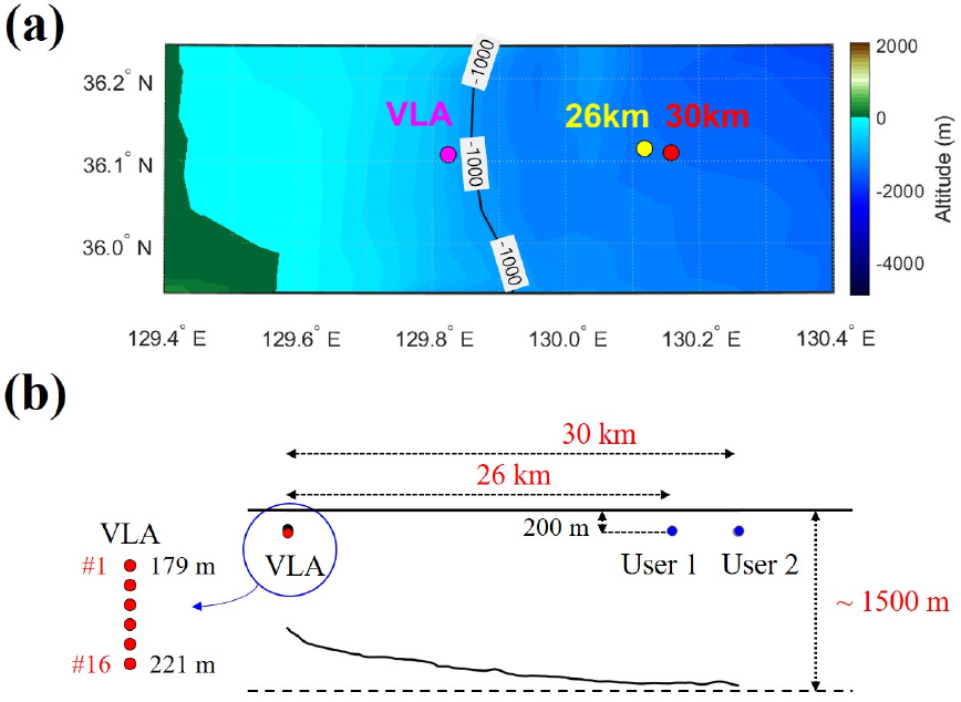
BLAC18 was conducted in the east of Pohang for four days from October 13 to 16, 2018. During BLAC18, the R/V Ieodo, owned by the Korea Institute of Ocean Science and Technology, was used. In the R/V Ieodo, both deployment and recovery of the source and receiver were carried out, and the source was connected to the ship, which was in a drift state. During the at-sea experiment, a vertical line array sensors was utilized as the receiver and moored to the seafloor using a weight. During the first two days (October 13-14), the experiment started with the source at approximately 30 km from the receiver, but the source moved closer, to approximately 26 km, due to the tides. For the remaining two days (October 15-16), signals were transmitted with the source at 30 km, 60 lm, and 90 km, and movement due to the tide was very small. The receiver was installed once every two days. In this study, to simulate the MIMO environment, data obtained at the range of 26 km in the first two days and at the range of 30 km for the other two days were synthesized; the positions of the two points and the receiver are presented in Fig. 1(a). Fig. 1(b) shows a schematic of the source and receiver locations and environmental information. The source was maintained at a depth of approximately 200 m. The vertical line array was deployed with the center depth of 200 m, and the design had the total length of 42 m, consisting of 16 channels at 2.8-m intervals. The depth of the seafloor at the receiver location was approximately 1,000 m, and the seabed topography showed that the depth of the seafloor increased to approximately 1,500 m in the range of 30 km.
The sound speed profiles were measured by Conductivity, Temperature, and Depth (CTD) in the R/V Ieodo. Fig. 2 presents the sound speed profiles measured at the receiver position and at two source positions (ranges of 26 km and 30 km), along with the depth of the source and receiver. The acoustic axis, an important factor for propagation in a long-range environment, was formed between depths of 230 m and 270 m.
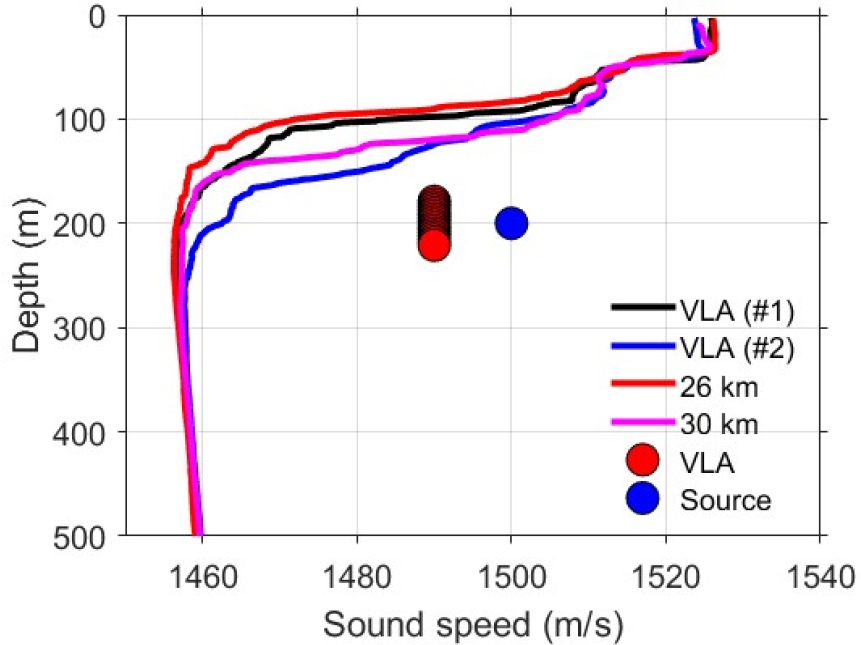
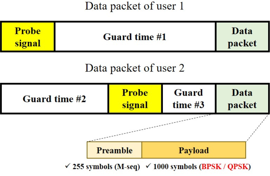
Fig. 3 shows the structure of the data packets in the MIMO environment. In Fig. 3, users 1 and 2 represent sources at 26 km and 30 km, respectively. The guard time was appropriately arranged to extract the channel impulse response from each source, and the signals were synthesized. As the MVDR-based adaptive signal processing method uses probe signals to estimate the channel impulse response, it is important that the probe signals are separated by using an appropriate guard time. Meanwhile, there was little resistance with respect to the timing of synthesizing the communication signals. Specifically, there is no need to match the starting points of the two communication signals. Hereinafter, sources at ranges of 26 km and 30 km are defined as user 1 and user 2, respectively, for convenience. The probe signals were designed as 3-s-long chirp signals with the Hanning window applied, and the carrier frequency and bandwidth were set to 2,560 Hz and 640 Hz, respectively. The data packet comprised an M-sequence signal with 255 symbols designed for synchronization and phase-locked loop and with 1,000 symbols as a payload. The payload was designed with the modulation schemes of BPSK and QPSK, and the first 100 symbols out of the 1,000 symbols were used as training symbols for the equalizer. The carrier frequency and bandwidth of the data packet were the same as those of the chirp signals, and pulse shaping was performed using a root-raised cosine filter with the roll-off factor of 0.25 to minimize ISI. The data rates for both BPSK and QPSK were 512 sps. There were three types of guard times between probe signals and communication signals (2.5 s, 5.5 s, and 8 s), and the designed signals were repeatedly transmitted nine times during the at-sea expeirment.
IV. Results of the at-sea experiment analysis
4.1 Channel impulse response
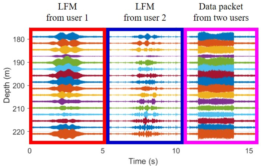
As described above, the signals at two ranges were synthesized to simulate the MIMO signal, and Fig. 4 shows the received signals synthesized based on the structure presented in Fig. 3. The red and blue boxes represent sections with probe signals from user 1 and user 2, respectively, and the magenta box represents the sections with synthesized data packets.
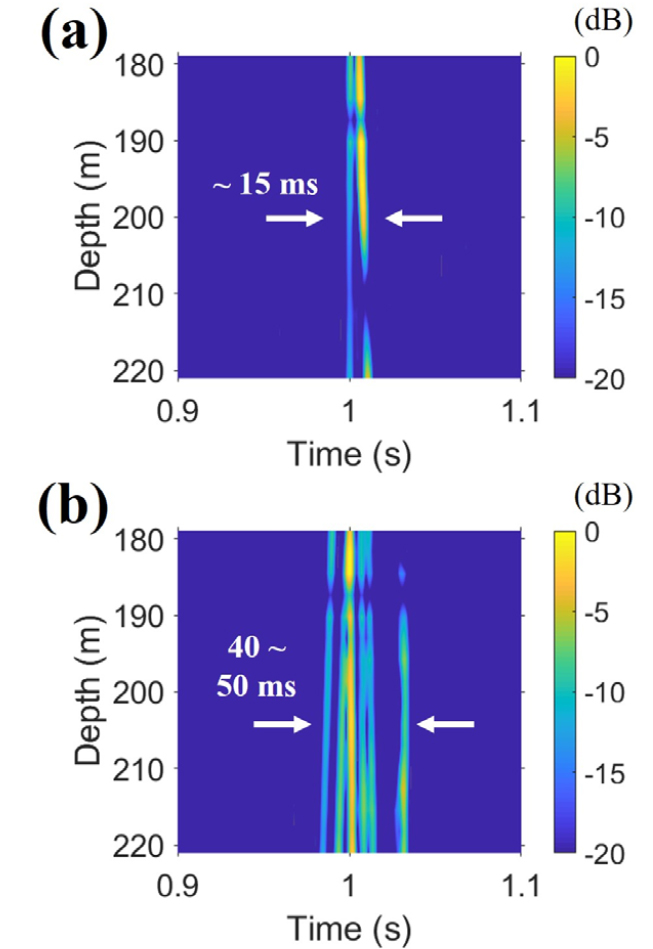
Channel impulse responses are required for conventional and adaptive passive TRP methods. Fig. 5 shows the channel impulse responses between the two users and the receiver. Fig. 5(a) displays the channel impulse response between user 1 and the receiver. There are two dominant paths, and the time delay due to both paths is confirmed to be less than 15 ms. Meanwhile, the channel impulse response of user 2 is presented in Fig. 5(b), and unlike user 1, it can be seen that the number of multipaths and the length of time delay increased. Because the channel impulse response changes with environment (e.g. sound speed profile, range, etc.), it is natural that the channel impulse responses differ.
4.2 Results of analysis based on passive TRP
Passive TRP is calculated as the correlation between the received signals and the channel impulse response; if the transmitted signals are separated from the received signals, it can be expressed as a combination of the auto- correlation between the channel impulse responses and cross-correlation. Song proposed a q-function using the correlation between channel impulses as an indicator of the TRP performance,[29] and Shimura applied the q- function in a MIMO environment.[15] In this study, the q-functions of the conventional and adaptive techniques used in Reference [15] were employed, and Eqs. (6) and (7) show the expressions of the q-functions of the conventional and adaptive techniques, respectively,
where and denote the user number; and denote the channel impulse response estimated at the th receiver and the processed weight vector, respectively. In addition, and can be obtained through the inverse Fourier transform after calculating the th component of and expressed in Eqs. (1) and (2) for all frequencies.
Fig. 6 shows a comparison of the q-function of the conventional and adaptive processing techniques, the results of which are represented by the black and red lines, respectively. Normalization was performed based on the maximum value of the four q-functions. Fig. 6(a) and 6(d) exhibit the q-function results for each source. Fig. 6(b) and 6(c), which show the q-functions between different sources, have a time-reversed relationship with each other. From the black line in Fig. 6(b) [or Fig. 6(c)], it can be seen that the channel impulse responses by the two sources have a low correlation. Therefore, it can be expected that communication performance reconstruction is possible to some extent when conventional passive TRP is applied to the data used in this study. However, because the two channel impulse responses are not exactly orthogonal, it can be seen that they exist as low-level noise during cross- correlation [black lines in Fig. 6(b) or 6(c)], which is equivalent to the interference from the other source appearing as noise, as described in Section 2.1. From a theoretical perspective, when the transmitted signal is applied to the results shown by the black lines in Fig. 6(a) and 6(b) and added, it corresponds to the case of with =1 in Eq. (1).
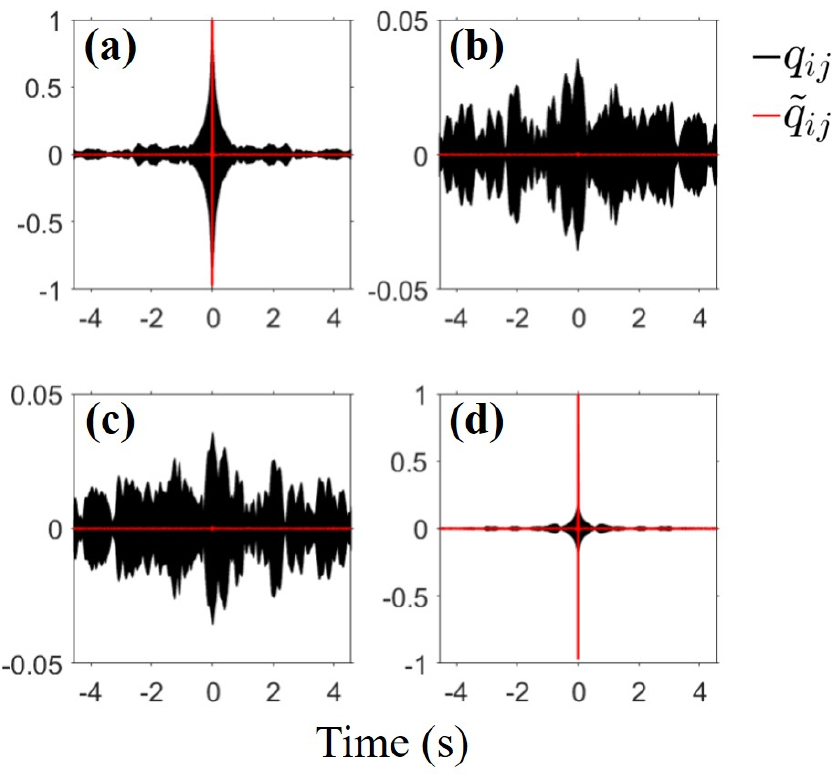
However, in the case of the conventional TRP, interference signals from other sources are included as noise, and communication performance can be improved when an adaptive signal processing technique that cancels the interference and noise is applied. Specifically, it can be expected that the output Signal to Noise Ratio (SNR) would be improved through cancellation of the interference signals, indicating a reduction in the distribution area of the estimated symbols; thus, a decrease in the Bit Error Rate (BER) can also be expected. The adaptive signal processing method passes the channel impulse response to the desired source with the magnitude of 1 for all frequencies, as shown in Eq. (3); in the time domain, the q-function is presented in the form of a delta function, indicated by the red lines in Fig. 6(a) and 6(d). When comparing the results of the conventional and adaptive TRP methods, the q-functions for the other source, Fig. 6(b) and 6(c), shows the largest difference. The weight vector processed for adaptive signal processing cancels the channel impulse response by the unwanted source by minimizing the power in a direction other than the direction of the selected source, as in Eq. (3). Taking the red line in Fig. 6(b) as an example, the correlation between the channel impulse response for user 2 and the weight vector that passes the channel impulse response for user 1 is calculated to be 0. The red line in Fig. 6(c) corresponds to the opposite case. From a theoretical perspective, when the transmitted signal is applied to the results shown by the red lines in Fig. 6(a) and 6(b) and added, it corresponds to the case of =1 in Eq. (2), and because the red lines in Fig. 6(a) and 6(b) become the delta function and 0, respectively, interference from the other source is cancelled. From the comparison of the results of conventional and adaptive processing, an improvement in the communication performance can be expected with application of the adaptive passive TRP.
Fig. 7 shows the scatter plots obtained by performing conventional passive TRP for each user and the modulation scheme. The upper row [Fig. 7(a) and Fig7(b)] displays the scatter plots for BPSK, and the lower row [Fig. 7(c) and 7(d)] presents the scatter plots for QSPK. In addition, the scatter plots on the left [Fig. 7(a) and 7(c)] and on the right [Fig. 7(b) and 7(d)] are for user 1 and 2, respectively. As expected from the result in Fig. 6, it can be seen that demodulation of the communication signal is successful even with the application of the conventional passive TRP. There was no bit error in the three cases other than the QPSK modulated signal of user 2, in which the BER of approximately 0.2 % was obtained. In terms of the output SNR, a value of 15 dB or more was obtained for user 1 and 10 dB or more for user 2. All BER and output SNR results in the conventional TRP environment are summarized in Tables 1 and 2, respectively. The lower the output SNR, the farther the estimated symbols are distributed with respect to the information symbols in the scatter plot. In the case of QPSK, compared with BPSK, the area for symbol decision in the scatter plot is reduced, indicating that the probability of bit error occurrence in QPSK modulated signals increases. Accordingly, it is judged that a bit error (37/16200) appeared in the QPSK modulated signals of user 2, unlike in the results of other cases.
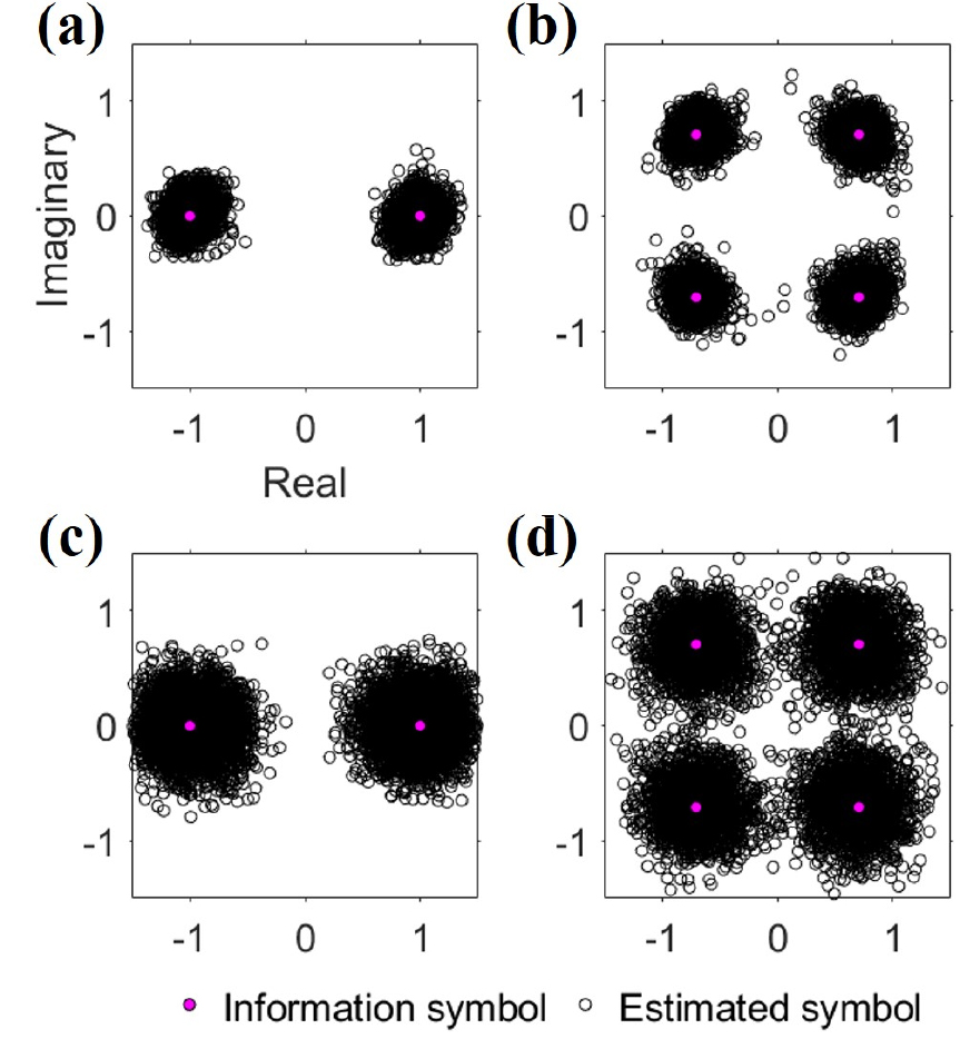
Table 1.
Bit error rates of all cases (modulation:BPSK and QPSK, conventional vs adaptive method).
| Modulation | User | Conventional | Adaptive |
| BPSK | 1 | 0/8100 | 0/8100 |
| 2 | 0/8100 | 0/8100 | |
| QPSK | 1 | 0/16200 | 0/16200 |
| 2 | 37/16200 | 0/16200 |
Table 2.
Output SNRs of all cases (modulation:BPSK and QPSK, conventional vs adaptive method) and the difference of output SNRs between two methods.
| Modulation | User | Conventional () | Adaptive () | |
| BPSK | 1 | 16.08 dB | 19.64 dB | + 3.56 dB |
| 2 | 10.43 dB | 15.90 dB | + 5.47 dB | |
| QPSK | 1 | 15.50 dB | 18.70 dB | + 3.20 dB |
| 2 | 10.10 dB | 15.75 dB | + 5.56 dB |
From Fig. 6, it can be seen that the weight vector for a specific source cancels the channel impulse response for the other source, and Fig. 8 shows the result of performing adaptive passive TRP using a weight vector to the received signals synthesized by two sources. When compared with the results in Fig. 7, the estimated symbols show a closer distribution to the information symbols in all the results in Fig. 8, indicating an enhancement in the output SNR. This is consistent with the prediction from the change in the q-function described above. The most pronounced difference can be observed in Fig. 8(d), the result of QPSK modulated signals of user 2, and through the application of adaptive passive TRP, the BER becomes 0 %. The data rates of the designed BPSK and QPSK were 512 sps, but by achieving 0 % BER for the MIMO environment with two sources, the data rates of BPSK and QPSK doubled to 1,024 sps.
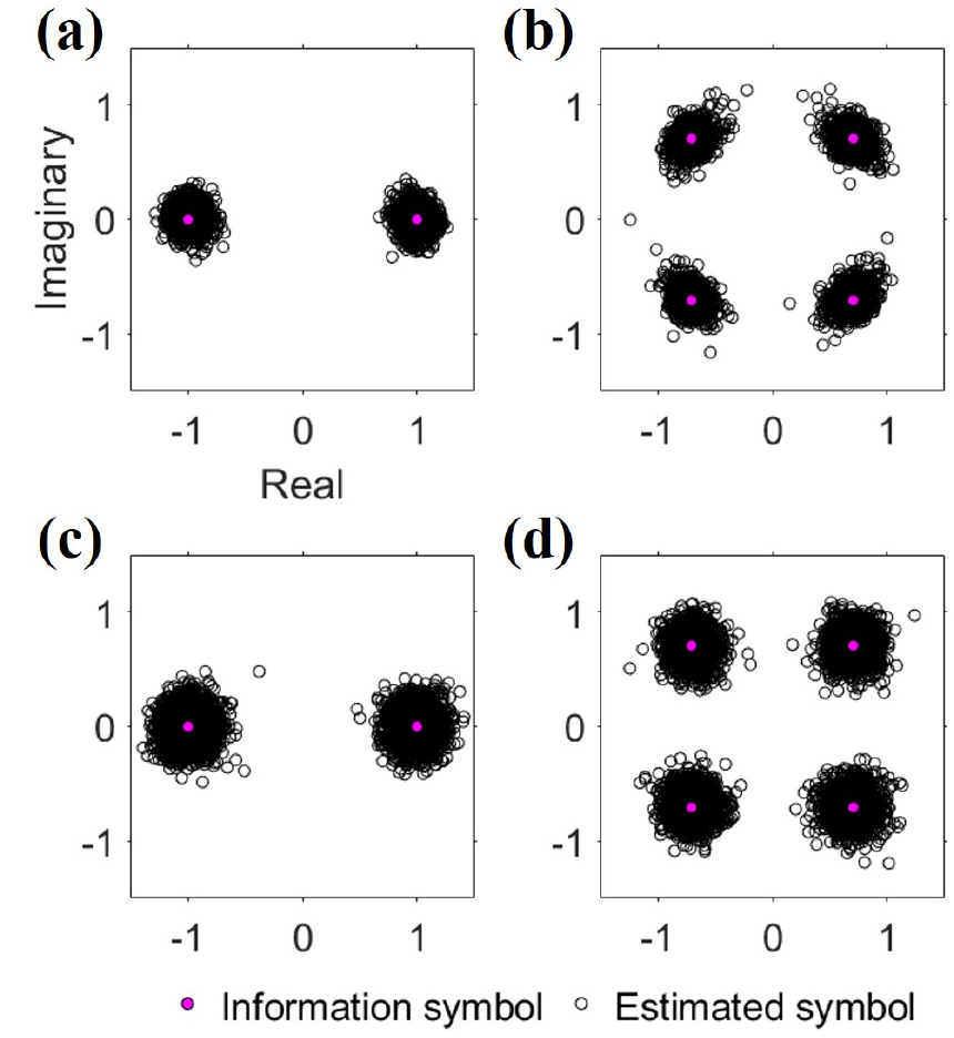
In addition, through adaptive passive TRP, the output SNR was increased for all cases (two sources and two modulation schemes), and the minimum increment was 3.20 dB. The BER and output SNR with the application of adaptive passive TRP are outlined in Tables 1 and 2, respectively.
From Table 2, it can be seen that when adaptive passive TRP was used instead of conventional passive TRP, the output SNR increased from the minimum of 3.20 dB to the maximum of 5.56 dB. On examining each user, the average increments of user 1 and 2 were found to be 3.38 and 5.52 dB, respectively, and the output SNR increment of user 2 was larger. For the average increment, a simple average value between the output SNRs of BPSK and QPSK was used for convenience, as shown in Eq. 8.
The reason for the difference in the average increment of the output SNR can be inferred from the changes shown in Fig. 6. Regarding the result of conventional processing shown in Fig. 6(c), the SNR was smaller compared with the result of conventional processing presented in Fig. 6(a); however, in the case of adaptive signal processing that maintains the distortionless response at the desired location, the two SNR results were similar. Specifically, in terms of the q-function, it can be seen that the SNR increment of the q-function of user 2 is larger than that of user 1 owing to the application of adaptive signal processing. Therefore, the output SNR improvement of user 2 data is enhanced further through the application of adaptive signal processing.
Owing to the low correlation between the channel impulse responses of the two sources, the effect of adaptive signal processing appeared insignificant with respect to BER performance, as the conventional signal processing already achieved satisfactory performance; however, in terms of the output SNR, the merit of adaptive signal processing, which cancels interference from other sources, was clearly confirmed.
V. Conclusions
In this study, communication performance analysis was performed on passive TRP in MIMO environments to improve the data rate in long-range environments. Passive TRP has the characteristics of a self-equalizer, but when there are two or more sources, there can be interference from other sources, which degrades the communication performance. To overcome this problem, an adaptive signal processing technique was applied. In this paper, we presente and compare the communication performance analysis results of the conventional and the adaptive signal processing techniques.
For analysis based on experimental data, BLAC18 data obtained from the east of Pohang in October 2018 were utilized, and the MIMO environment was simulated by synthesizing data in the range of 26 km (user 1) and 30 km (user 2). During the experiment, signals designed using the modulation schemes of BPSK and QPSK were transmitted.
As a result of applying the simulated MIMO data to conventional passive TRP, the BER of 0 % was obtained, except for the QPSK data of user 2 (37/16200, 0.23 %), indicating that the conventional passive TRP method was effective in terms of BER performance. However, from the analysis of the q-function, one of the performance indicators of TRP, interference between sources was confirmed. To cancel the interference, an MVDR-based adaptive signal processing technique was applied to the data. Owing to the effect of adaptive signal processing, which cancels interference from other sources and noise, the BER of 0 % was also obtained for the QPSK data of user 2, and improvement in output SNR was confirmed. The effect of adaptive signal processing may appear insignificant with respect to BER; however, in terms of output SNR, the effect was confirmed, and the output SNR improved by 3.52 dB at minimum and 5.56 dB at maximum. The output SNRs of user 1 and user 2 improved by 3.38 dB and 5.52 dB on average, respectively.
For a long-range environment with limitations of low data rate, only studies of a single source environment have been published in Korea, but the results of this study demonstrate the feasibility of using MIMO to increase the data rate. Furthermore, it is expected that further studies can be performed, such as the application of various adaptive signal processing techniques, application to a long-range environment of more than 30 km, and investigation of a multi-source environment with different depths.
